Exchange the UPS

Before you begin

CAUTION:
This assembly contains mechanical moving parts. Use care when you service this assembly. (C025)

Icon for electrostatic discharge wrist strapUse approved ESD procedures to prevent damage.

Attention:
  • This procedure is not a stand-alone procedure. Customer disruption and damage to the hardware might occur when microcode and power boundaries are not in the proper conditions for this service action.
  • If a serviceable event FRU repair directed you to this procedure, the microcode and power boundaries are already set.
  • If a serviceable event FRU repair did not direct you to this procedure, see MAP1230 Replace a FRU without using a serviceable event.
Notes:
  • All the cables and FRUs to be removed must be uniquely identified so they can be reinstalled correctly.
  • If an installed earthquake resistance kit prevents you from accessing this FRU, refer to MAP1600.

Remove the UPS

Procedure

  1. The UPS FRU should have arrived with a new battery FRU, in a separate box. Check the date labels on the FRU packaging or on the front of the new battery FRU.
    1. Record the "Install / Recharge by: " date for reference at a later screen.
    2. Record the "Battery Mfg. Date" for reference at a later screen.
      Note: Both dates appear in the format YYYY-MM-DD. Later in this repair you will be asked to enter the "Battery Mfg. Date" in the format YYYYMM.
    3. Has the "Install / Recharge by: " date passed?

      Yes. The date has passed. Stop the repair. You cannot continue with an expired battery FRU.

      • Click Close to close the parts exchange procedure.
      • When asked, "Has the part been replaced?", click OK.
      • When directed to check "Install / Recharge by: " date, click Exit to exit the service action.

      No. The date has not passed. Continue the repair.

  2. Locate the UPS to be replaced.
    1. There is no FRU identify LED indicator for the UPS.
    2. The UPS is part of the storage controller module, the group of enclosures shown in Figure 1.
    3. You must use the FRU location code information to locate the FRU.

      The location code is in the format Unnnn.mmm.ssssss-E6y. Example:
      nnnn = machine type
      mmm = model
      sssssss = storage facility serial number (Not the serial number of the customer-provided rack.)
      y = 1 (upper), 2 (lower)
      See Figure 1.

    4. Use the storage facility serial number label on the front of the management enclosure to confirm.
    Figure 1. Storage controller module (enclosures shown)
    Storage controller module (enclosures shown)
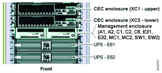
    Figure 2. Management enclosure front panel
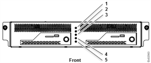
    Management enclosure front panel
  3. Power off the UPS.
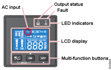
    1. At the UPS control panel, press the OFF button for 3 seconds and release it after one beep. See Figure 3.
      Figure 3. UPS control panel
      UPS control panel
    2. Wait 30 seconds. Is the UPS control panel output status green LED indicator off? See Figure 3.
      Note: The control panel displays oFF status.
      • Yes. Go to step 4 to disconnect the input power cable.
      • No. The UPS cannot power down normally. Go to step 4 to force power off (by disconnecting the input power cable).
  4. At the rear of the UPS, unplug the input power cable from J10. See Figure 4.
    Warning: An immediate customer outage will occur if the input power cable is unplugged from the wrong UPS.
    1. Loosen, but do not remove, the cable retention bracket screw Callout label 1 and lift up to remove the bracket Callout label 2. See Figure 5.
    2. Unplug the cable.
    Figure 4. UPS connectors (rear view)
    Location codes for the UPS (Model 983), rear view
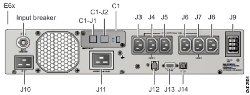
    Figure 5. UPS input power cable retention bracket (rear)
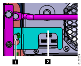
    UPS input power cable retention bracket (rear)
  5. Wait up to 5 minutes until the control panel changes to dark.
    Note: The UPS is temporarily powered by the battery until the "On battery" condition times out.
  6. Remove the UPS front panel and disconnect the control panel cables from the UPS.
    1. Remove the four screws. See Figure 6.
      Note: The screws are small and are not fastened to the front panel. Use caution to avoid dropping the screws.
    2. Partially remove the front panel.
    3. Disconnect the control panel cables from the UPS.
      Note: Handle with care to avoid damaging the connecting cables.
    4. Remove the UPS front panel. It is reinstalled on this UPS after the battery is removed from the UPS and the UPS is removed from the rack.
    Figure 6. UPS front panel screws.
    Front panel and screws
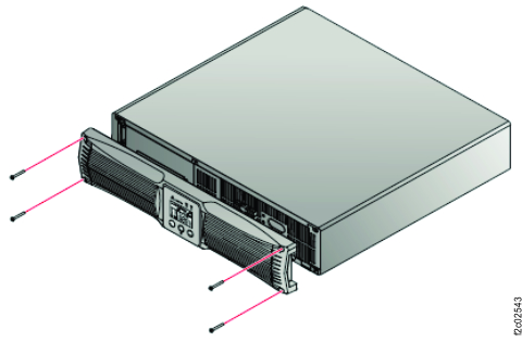
  7. Disconnect the battery cables connector. See Figure 7.
    Note: This might require cutting the tie wrap on the right side of the battery retainer bracket.
    Figure 7. UPS battery cables connector
    Battery cable connectors
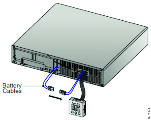
  8. Remove the two screws and battery retainer bracket. See Figure 8.
    Note: The screws are small and not fastened to the bracket. Use caution to avoid dropping the screws.
    Figure 8. UPS battery retainer bracket screws
    Battery bracket and screws
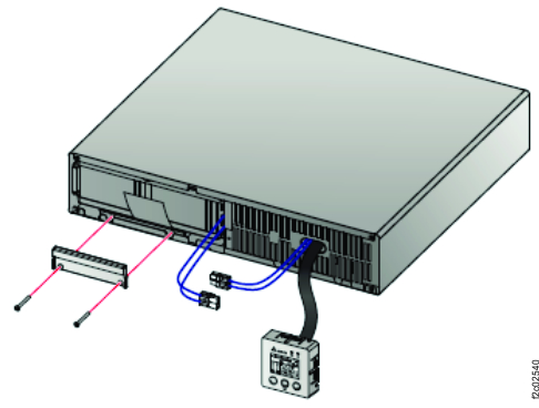
  9. Carefully pull out the battery tab and remove the battery. See Figure 9.
    Figure 9. UPS battery tab and battery
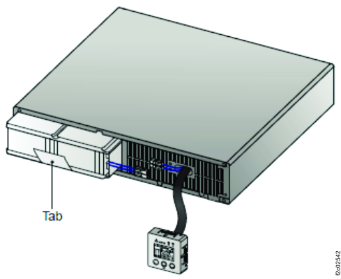
    Battery tab
  10. At the rear of the UPS, ensure that all cables are properly labeled, remove the hook-and-loop cable ties from the cable tie bar as needed, and disconnect the cables. See Figure 4.
  11. At the rear, remove the upper 2 screws Callout label 1 and remove the cable tie bar Callout label 2. See Figure 10.
    Figure 10. UPS front cable tie bar
    UPS power cable tie bar
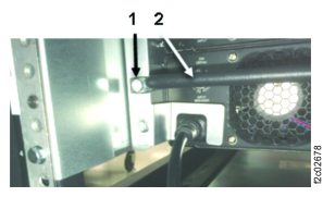
  12. At the rear, remove the lower two screws. See Figure 11 and Figure 12.
    Figure 11. UPS mainline power cable retention bracket (rear)
    UPS mainline power cable retention bracket (rear)
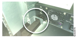
    Figure 12. UPS lower right screw
    UPS lower right screw
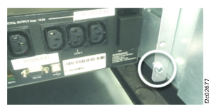
  13. At the front of the rack, remove the two screws (white circle). See Figure 13.
    Figure 13. UPS front screws
    UPS rail (front left)
  14. Remove the UPS from the rack.
    CAUTION:
    The combined weight of the UPS with battery exceeds the single-person weight limit.
  15. Reinstall the front panel on the UPS.
    Note: The battery is returned or disposed of separately. The old battery is not reused.

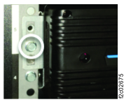
Transfer network card from old to new UPS

Procedure

  1. At the rear of the UPS, remove the network card (C1). See Figure 4.
    1. Remove the dust plug from C1-J2.
    2. Remove the two screws.
    3. Remove the black plastic bezel.
    4. Remove the network card. Note the orientation of the network card.
      Note: If the card is hard to remove, a spare Ethernet cable can be connected to the network port (C1-J1) and pulled to remove the card.
    Note: The network card is hot-plugged. The UPS stays fully operational.
  2. To install the network card in the new UPS, reverse the steps above.

Transfer UPS 1U side rails from old to new UPS

Procedure

  1. If the new UPS did not come with side rails pre-installed, transfer the rails from the old UPS to the new UPS.
    Each rail is fastened with 10 screws Callout label 1. See Figure 14.
    Figure 14. UPS 1U rail, left
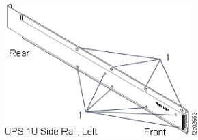
    UPS 1U side rail screw holes (outside view)
  2. Install the side rails on the new UPS.

Install the UPS

Procedure

  1. Temporarily remove the front panel from the new UPS FRU. Set it aside.
    1. Remove the four screws. See Figure 6.
      Note: The screws are small and are not fastened to the front panel. Use caution to avoid dropping the screws.
    2. Partially remove the front panel.
    3. Disconnect the control panel cables from the UPS.
      Note: Handle with care to avoid damaging the connecting cables.
    4. Remove the UPS front panel.
  2. If spare labels were provided with the FRU kit, create a system serial number and UPS location cable label to affix to the top from edge of the new UPS.
    1. On the top front edge of the old UPS, find the existing white labels with the system serial number (S/N) and UPS Enclosure location. See Figure 15.
    2. Find the blank label shipped with the new UPS.
    3. Write the system S/N and UPS location on the new label. Fasten it to the new UPS in the same location as the old UPS.
    Figure 15. Storage facility serial number label location
    Enclosure labels (example)
  3. Ensure that the new UPS does not have a battery installed. The new battery FRU is in a separate box.
    Note: If the new FRU has a battery installed, remove it.
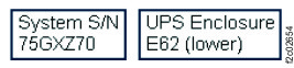
  4. Install the new UPS (without battery) in the rack and fasten with the two screws Callout label 4. See Figure 13.
    CAUTION:
    The combined weight of the UPS with battery exceeds the single-person weight limit.
  5. At the rear, install the four screws. Ensure that the cable tie bar is in the upper position.
  6. At the front of the new battery FRU, check the front label(s) if you have not already done so.
    1. Record the "Install / Recharge by: " date for reference at a later screen.
    2. Record the "Battery Mfg. Date" for reference at a later screen.
    Note: Both dates appear in the format YYYY-MM-DD. Later in this repair you will be asked to enter the "Battery Mfg. Date" in the format YYYYMM.
  7. Install the new UPS battery in the UPS.
    1. Place the new UPS battery in the UPS and install the retainer bracket with screws. See Figure 8.
    2. Connect the battery cables. See Figure 7.
    3. Connect the control panel cables.
    4. Reinstall the front panel with four screws. See Figure 6.
  8. At the rear of the rack, connect all cables except the power input cable J10. See Figure 4.
    Secure each power output cable (J3-J8) to the cable tie bar using the hook-and-loop fasteners.
  9. At the rear of the rack, connect the power input cable J10 and install the cable retention bracket. See Figure 5.
  10. Wait up to 2 minutes for the UPS control panel to display status. Select the following that applies. See Table 1.
    Table 1. UPS J10 power connection state on control panel
    Output Status Green LED
    (Figure 16)
    AC icon
    (Figure 17)
    UPS State Go to:
    On On On Step 13
    Off On Standby Step 11
    Off Off Off Step 12
    Figure 16. UPS control panel
    UPS control panel
    Figure 17. UPS control panel LCD display AC icon (upper left)
    AC icon
  11. Standby state indication. Power on the UPS.
    1. Press the UPS control panel Power button for 3 seconds and release it after it beeps.
    2. Wait up to 2 minutes for the Output status green LED to be ON. See Figure 16.
    3. If the UPS Output status green LED is on, go to step 13.
    4. If the UPS Output status green LED is off, observe the AC icon.
      • If the AC icon is on, the UPS is stuck in standby mode. Exit this MAP and replace the UPS.
      • If the AC icon is off, return to step 9.
  12. Off state indication.
    1. If the UPS input breaker above connector J10 is tripped, replace the UPS or reset the breaker and return to step 10.
    2. If the UPS mainline power cable at the UPS J10 connector and the source power connector is not connected properly, correct the problem and return to step 10.
    3. Ensure that the source power connector has power. If it does not, correct the problem and return to step 10.
    4. If the UPS is receiving power, exit this MAP and replace the UPS.
  13. Exit this service information center parts exchange procedure and return to the procedure that sent you here.