Exchange the UPS network card
Before you begin
CAUTION:
This assembly contains mechanical moving parts. Use care when
you service this assembly. (C025)
 Use approved ESD procedures to prevent damage.
Attention:
- This procedure is not a stand-alone procedure. Customer disruption and damage to the hardware might occur when microcode and power boundaries are not in the proper conditions for this service action.
- If a serviceable event FRU repair directed you to this procedure, the microcode and power boundaries are already set.
- If a serviceable event FRU repair did not direct you to this procedure, see MAP1230 Replace a FRU without using a serviceable event.
Notes:
- All the cables and FRUs to be removed must be uniquely identified so they can be reinstalled correctly.
- If an installed earthquake resistance kit prevents you from accessing this FRU, refer to MAP1600.
Remove the UPS network card
Procedure
-
Locate the UPS with the UPS network card to be replaced.
-
The amber system identify LED on the management enclosure (
 , Figure 1) is flashing.
Figure 1. Management enclosure front panel 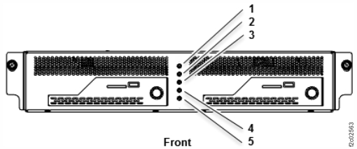
Figure 2. Storage controller module (enclosures shown) 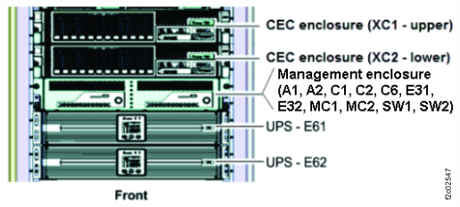
-
The amber system identify LED on the management enclosure (
-
At the rear of the UPS, remove the network card (E6x-C1). See Figure 3.
Note: The network card is hot-plugged. The UPS stays fully operational.
Figure 3. UPS connectors (rear view) 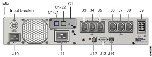
Install the UPS network card
Procedure
-
Set the new network card DIP switches to OFF. See Figure 4 and Figure 5.
Figure 4. Locations for the UPS network card (Model 983) 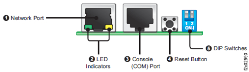
Figure 5. DIP switches for the UPS network card (Model 983) 
-
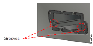
Install the network card in the UPS. See Figure 6.
- Slide it fully into the grooves.
- Replace the black plastic bezel.
- Install the two screws.
- Install a dust plug in C1-J2.
Figure 6. UPS network card slot grooves