Checking cables on all racks
Procedure
-
At the rear of Rack-1, do the following steps at the rear of both CEC enclosures:
-
Ensure that the following private network Ethernet cables are connected:
- Model 982, 988
-
- A black Ethernet cable is connected to P1-C5-T4 (HMC port 1 - left) and P1-C11-T1 (top).
- A gray Ethernet cable is connected to P1-C5-T5 (HMC port 2 - right) and P1-C11-T2 (second from top).
- Model 981, 985, 986
-
- A black Ethernet cable is connected to P1-T3 (HMC1 - upper) and P1-C10-T1 (top).
- A gray Ethernet cable is connected to P1-T4 (HMC2 - lower) and P1-C10-T2 (second from top).
- Model 980, 984
-
- A black Ethernet cable is connected to P1-T1 (HMC1 - upper) and P1-C10-T1 (top).
- A gray Ethernet cable is connected to P1-T2 (HMC2 - lower) and P1-C10-T2 (second from top).
Figure 1. CEC enclosure location codes (rear view) (Models 982, 988) 
Figure 2. CEC enclosure location codes (rear view) (Models 981, 985, and 986) 
Figure 3. CEC enclosure location codes (rear view) (Models 980 and 984) 
-
Ensure that the following private network Ethernet cables are connected:
-
At the rear of each I/O enclosure for Rack-1 and Rack-2 (if present), gently push on each PCIe
cable (P1-C7-T1 and P1-C7-T2; also, P1-C7-T5 or P1-C7-T6, if present) to ensure that it is latched.
See Figure 4.
- If Rack-2 has a coil of PCIe and PCN cables behind the I/O enclosures, loosen the cable tie at the top of the coil and move it temporarily out of the way.
Figure 4. I/O enclosure locations (rear) (models 98x, 8xE) 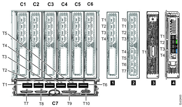 Note: The older generation I/O enclosure PCIe and PCN card might not include T3, T4, and T10 ports.
 -
At the rear of each rack, ensure all power cables that are connected to each power
distribution unit (PDU) connector J1-J12 are fully seated. See Figure 5.
Figure 5. Locations for power distribution unit (PDU) connectors