Disconnecting the flash PCIe cables in the rack being installed
Procedure
-
At the rear of Rack-2, disconnect the storage enclosure PCIe cables from all I/O enclosure PCIe
storage interface ports R2-XIn-P1-C7-T5 and T6. See Figure 1 and Figure 2. These cables are reconnected
later when the flash enclosures are installed.
Attention: Do not disconnect CEC enclosure PCIe cables from the I/O enclosure PCIe and PCN card ports R2-XIn-P1-C7-T1 and T2.
Figure 1. Point-to-point cabling diagram for storage enclosure Flash PCIe / SAS cables (Models 988, 88E, rear view, racks 1, 2) 
Figure 2. I/O enclosure locations (rear) (models 98x) 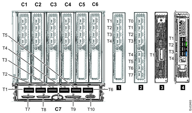
-
At the rear of Rack-2, firmly push on each flash PCIe cable that is connected to microbay
adapter cards C1 and C2 in microbay trays M06, M08, M10, M12 to ensure that they are connected. The
trays are located behind flash enclosures F06, F08, F10, F12. See Figure 1 and Figure 3.
Figure 3. Flash SAS cable connectors - Microbay adapter card (Cx-T1, T2, T3, T4) 
-
At the rear of Rack-2, disconnect the storage enclosure PCIe cables from all I/O enclosure PCIe
storage interface ports R2-XIn-P1-C7-T5 and T6. See Figure 4, Figure 5, Figure 6, , Figure 7, Figure 8, and Figure 9. These cables are reconnected
later when the flash enclosures are installed.
Attention: Do not disconnect CEC enclosure PCIe cables from the I/O enclosure PCIe and PCN card ports R2-XIn-P1-C7-T1 and T2.
Figure 4. Point-to-point cabling diagram for storage enclosure FC-AL and Flash PCIe / SAS cables (Models 985, 85E, single-phase power, rear view, racks 1, 2) 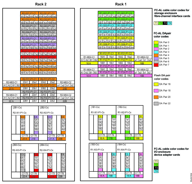
Figure 5. Point-to-point cabling diagram for storage enclosure FC-AL and Flash PCIe / SAS cables (Models 986, 86E, three-phase power, rear view, racks 1, 2) 
Figure 6. Point-to-point cabling diagram for storage enclosure FC-AL and Flash PCIe / SAS cables (Models 984, 84E, rear view, racks 1, 2) 
Figure 7. Point-to-point cabling diagram for storage enclosure Flash PCIe / SAS cables (Models 985, 85E all-flash, single-phase power, rear view, racks 1, 2) 
Figure 8. Point-to-point cabling diagram for storage enclosure Flash PCIe / SAS cables (Models 986, 86E all-flash, three-phase power, rear view, racks 1, 2) 
Figure 9. I/O enclosure locations (rear) (models 98x)
-
At the rear of Rack-2, firmly push on each flash PCIe cable that is connected to microbay
adapter cards C1 and C2 in the microbay trays to ensure that they are connected.
- For all-flash models 85E and 86E, the trays are located behind flash enclosures F02, F04, F06, and F08. See Figure 7, Figure 8, and Figure 10.
- For standard models 84E, 85E, and 86E, the trays are located behind flash enclosures F02 and F04. See Figure 4, Figure 5, Figure 6, and Figure 10.
Figure 10. Flash SAS cable connectors - Microbay adapter card (Cx-T1, T2, T3, T4)