Exchange the Ethernet switch to management console Ethernet cable
Before you begin
 Use approved ESD procedures to prevent damage.
Attention:
- This procedure is not a stand-alone procedure. Customer disruption and damage to the hardware might occur when microcode and power boundaries are not in the proper conditions for this service action.
- If a serviceable event FRU repair directed you to this procedure, the microcode and power boundaries are already set.
- If a serviceable event FRU repair did not direct you to this procedure, see MAP1230 Replace a FRU without using a serviceable event.
Note: All the cables and FRUs to be removed must be uniquely identified so they can be reinstalled
correctly.
Remove the Ethernet switch to CEC enclosure Ethernet cable
Procedure
-
At the front of the rack, slide the management enclosure out to the service position and remove
the top cover.
Note: The management enclosure is below the two CEC enclosures.
- Fully loosen the left and right captive thumb screws.
- Slide the management out fully so the sliding rails lock into place.
- At the rear of the top cover, fully loosen the left and right captive thumb screws.
- Slide the cover back until it lifts off.
Figure 1. Management enclosure (front) 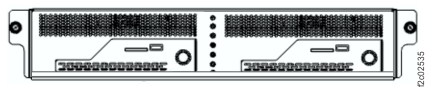
-
Locate the Ethernet cable.
-
Two gray Ethernet cables are between the lower (SW2) Ethernet switch and the management
enclosures. See Table 2, Figure 2, Figure 3, and Figure 4.
Table 2. Ethernet cables, SW2 (lower) (gray network) From SW2 Ethernet switch port To management console Management console (viewed from front of rack) SW2-T7 MC1-eth3 Left SW2-T8 MC2-eth3 Right Figure 2. Ethernet network locations (Model 983) Note: Upper switch SW1 is "black" network; lower switch SW2 is "gray" network.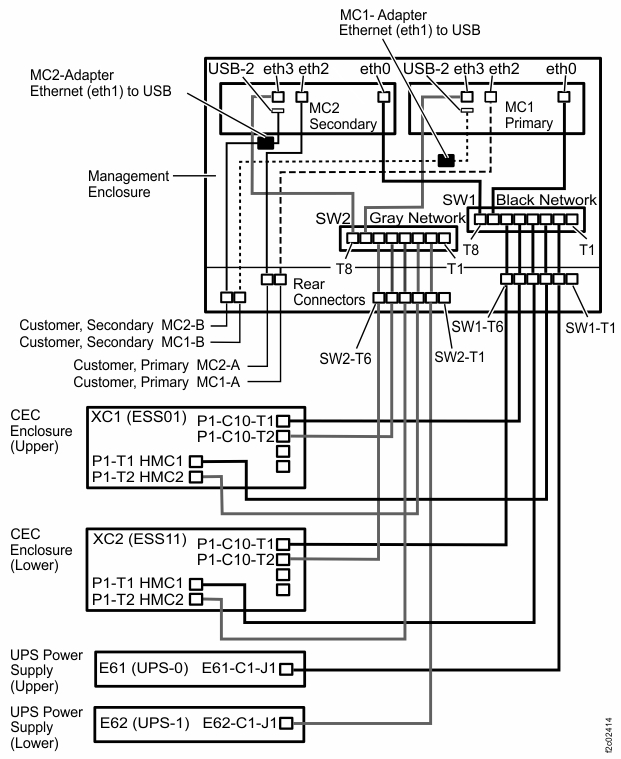
Figure 3. Management console locations (Model 983) 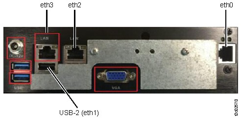
Figure 4. Management enclosure locations (Model 983) 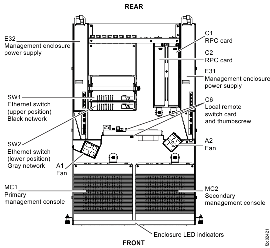
-
Two gray Ethernet cables are between the lower (SW2) Ethernet switch and the management
enclosures. See Table 2, Figure 2, Figure 3, and Figure 4.
Install the Ethernet switch to management console Ethernet cable
Procedure
- Use the location code label on each end of the cable to ensure it is installed correctly.
- Route the cable and connect both ends.
- Reinstall the cable retention hardware.
- To verify the black and gray private networks, refer to MAP7001 Using the network topology tool.
- Exit this service information center parts exchange procedure and return to the procedure that sent you here.