Exchange the PJA to PJA cable
Before you begin
 Use approved ESD procedures to prevent damage.
Attention:
- This procedure is not a stand-alone procedure. Customer disruption and damage to the hardware might occur when microcode and power boundaries are not in the proper conditions for this service action.
- If a serviceable event FRU repair directed you to this procedure, the microcode and power boundaries are already set.
- If a serviceable event FRU repair did not direct you to this procedure, see MAP1230 Replace a FRU without using a serviceable event.
Notes:
- All the cables and FRUs to be removed must be uniquely identified so they can be reinstalled correctly.
- If an installed earthquake resistance kit prevents you from accessing this FRU, refer to MAP1600.
Remove the PJA to PJA cable
Procedure
- At the rear of the rack, locate the PJA to PJA cable. Use
the location code, E41-J9 to E42-J9. See Figure 1, Figure 2, and Figure 3.
Figure 1. Ethernet switch tray locations (Model 961, rack version 1) 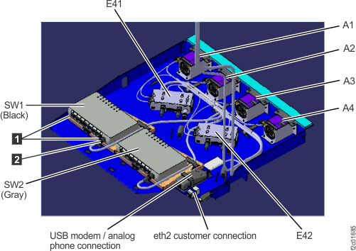
Figure 2. Ethernet switch tray locations (Model 961 rack version 2 rear) 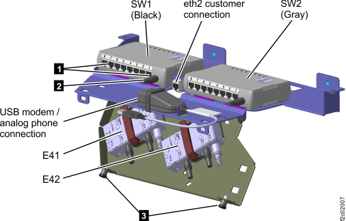
Figure 3. Power junction assembly (PJA) locations 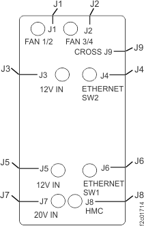
Install the PJA to PJA cable
Procedure
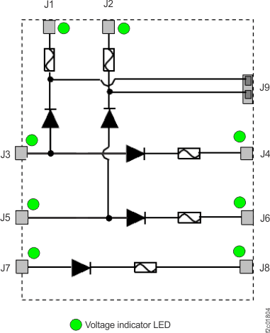
- A failure of this FRU is not isolated by code, and it cannot
be isolated by a visual symptom using the PJA LED indicators with
all cables connected. The only way to prove it is working is to disconnect
the J3 and J5 input connectors and then observe the J1 and J2 LED
indicators. If they are lit, the PJA to PJA cable (J9 to J9) is working
correctly and the J3 and J5 input cables can be reconnected. See Figure 4.
Figure 4. PJA internal diodes, fuses, LEDs