Routing and connecting the expansion rack SAS cables
Procedure
-
Determine the destination rack and I/O enclosure for each SAS cable.
- Find the location code label at the free end of each SAS cable.
- Refer to Figure 1 and Figure 2 to translate the destination I/O enclosure location.
Figure 1. Point-to-point cabling diagram for storage enclosure Flash PCIe / SAS cables (Models 988, 88E, rear view, racks 1, 2) 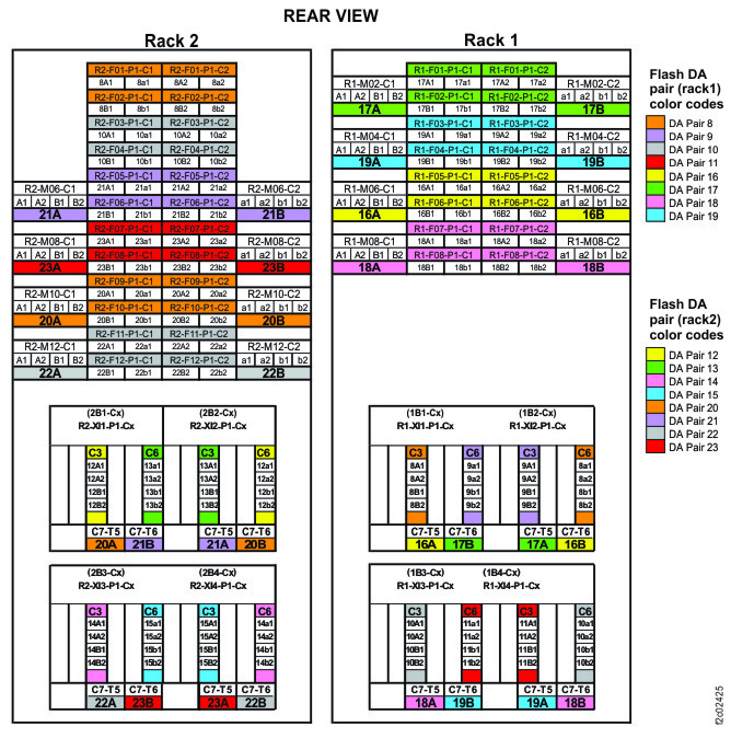
Figure 2. Point-to-point cabling diagram for storage enclosure Flash PCIe / SAS cables (Models 988, 88E, rear view, rack 3) 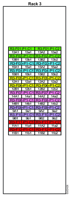
-
Route the SAS cables to the destination rack.
-
Route each cable 1 to the destination rack through the rack to
rack holes at the upper rear of each rack. See and Figure 3 and Figure 4.
Figure 3. Routing remote power control cables and optical cables between racks Note: Models 980 and 98B shown, routing for other models is similar
Figure 4. Routing rack-to-rack power control and optical cables across a rack (earlier model shown, routing for models 98x and 8xE similar) 
-
Route each cable 1 to the destination rack through the rack to
rack holes at the upper rear of each rack. See and Figure 3 and Figure 4.
-
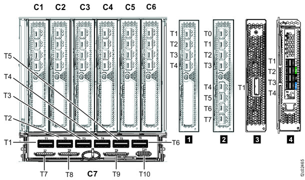
Plug the SAS cables into the connectors on the I/O enclosure device adapter cards as indicated
on the cable labels. Refer to Figure 5 and Figure 6 for connector locations.
Figure 5. I/O enclosure locations (rear)  Note: Enclosures 1B1, 1B2, 2B1, and 2B2 are not present in models 980, 984 (except all-flash), 98B, 84E.
Figure 6. I/O enclosure locations (rear) (models 98x, 8xE)