Rack power and cooling location codes (Models 961, 96E)
Use Table 1 to find
the part of the rack power and cooling system for which you seek location
code information. For part numbers, see Rack power and cooling part numbers, Models 951, 95E.
| Part | See |
|---|---|
| Overview of locations, base rack | Figure 1 |
| Overview of locations, expansion rack | Figure 2 |
| Battery service module set locations (front) | Figure 4 Figure 5 Figure 6 |
| DC-UPS locations (rear) | Figure 3 |
| DC-UPS locations (front) | Figure 4 |
| Ethernet switch tray (switches, fans, power
junction assembly) Laptop tray (fans) |
Figure 12 Figure 13 Figure 14 |
| Local remote switch card | Figure 7 |
| Power supplies, 20V and 12V for laptop, Ethernet tray fans, Ethernet switches | Figure 14 Figure 16 Figure 17 |
| Power junction assemblies (PJA) | Figure 15 |
| Power distribution unit (PDU) | Figure 11 |
| Rack identity card | Figure 9 |
| RPC card | Figure 10 |
| System z® local remote switch card | Figure 8 |
Overview of locations, base rack
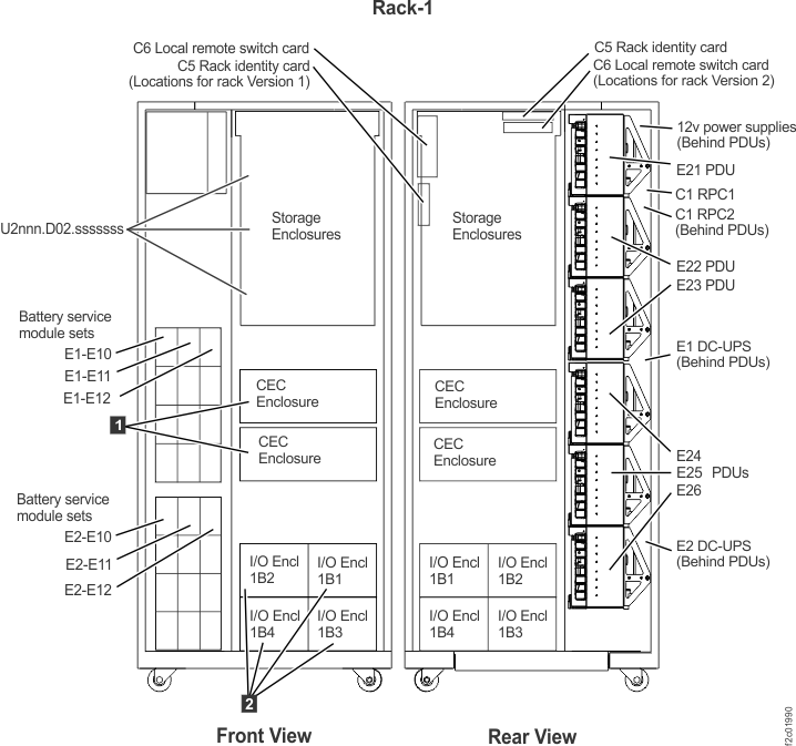
| Location code | Part name |
|---|---|
| U2nnn.mmm.sssssss-E1 | DC-UPS (upper) |
| U2nnn.mmm.sssssss-E1-Exx (xx = 10 thru 12) |
Battery service module set |
| U2nnn.mmm.sssssss-E2 | DC-UPS (lower) |
| U2nnn.mmm.sssssss-E2-Exx (xx = 10 thru 12) |
Battery service module set |
| U2nnn.mmm.sssssss-Exx (xx = 21 thru 26) |
Power distribution units |
 Un Un(Un = U78AA.001.sssssss) |
CEC enclosure |
 U1400.rBn.sssssss U1400.rBn.sssssss |
I/O enclosure |
| U2nnn.D02.sssssss | Storage enclosure |
Overview of locations, expansion rack
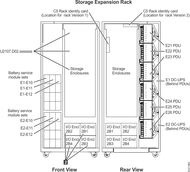
| Location code | Part name |
|---|---|
| U2nnn.mmm.sssssss-E1 | DC-UPS |
| U2nnn.mmm.sssssss-E1-Exx (xx = 10 thru 12) |
Battery service module set |
| U2nnn.mmm.sssssss-E2 | DC-UPS |
| U2nnn.mmm.sssssss-E2-Exx (xx = 10 thru 12) |
Battery service module set |
| U2nnn.mmm.sssssss-Exx (xx = 21 thru 26) |
Power distribution units |
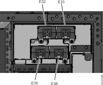
DC-UPS locations (rear)
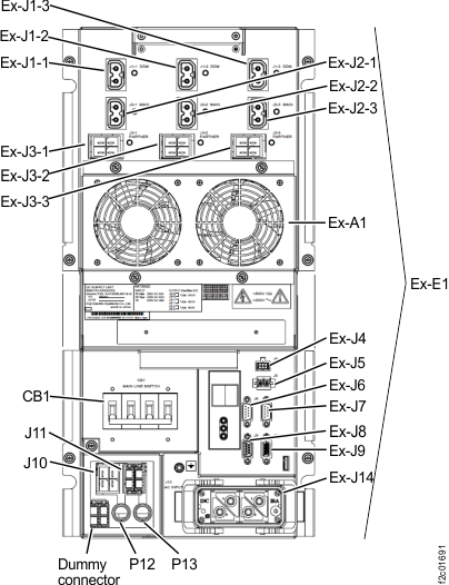
| Location code | Part name | Connector |
|---|---|---|
| U2nnn.mmm.sssssss-Ex1, 2 | DC-UPS (sheetmetal only enclosure, not a FRU) | |
| U2nnn.mmm.sssssss-Ex-A1 | DC-UPS fan assembly | |
| U2nnn.mmm.sssssss-Ex-E1 | DC supply unit | |
| U2nnn.mmm.sssssss-Ex-J1 | PDU | |
| U2nnn.mmm.sssssss-Ex-J2 | PDU | |
| U2nnn.mmm.sssssss-Ex-J3 | DC-UPS | |
| U2nnn.mmm.sssssss-Ex-J4 | DC-UPS fan assembly | |
| U2nnn.mmm.sssssss-Ex-J5 | DC-UPS, EPO switch | |
| U2nnn.mmm.sssssss-Ex-J6 | DC-UPS, RPC card C1 | |
| U2nnn.mmm.sssssss-Ex-J7 | DC-UPS, RPC card C2 | |
| U2nnn.mmm.sssssss-Ex-J8 | Not used (Rack 1) Rack Identity Card C5 (expansion rack) |
|
| U2nnn.mmm.sssssss-Ex-J9 | DC-UPS | |
| U2nnn.mmm.sssssss-Ex-J10 | Input phase selection | |
| U2nnn.mmm.sssssss-Ex-J11 | Input phase selection | |
| U2nnn.mmm.sssssss-Ex-J14 | Mainline power | |
| U2nnn.mmm.sssssss-Ex-P12 | (Input phase selection cable) | |
| U2nnn.mmm.sssssss-Ex-P13 | (Input phase selection cable) | |
Notes:
|
||
Battery service module set locations, DC-UPS (front)
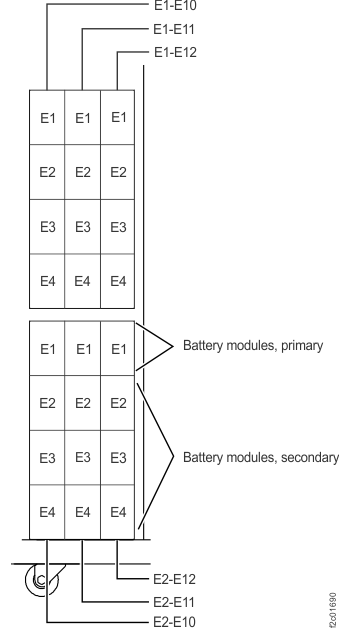
| Location code | Part name | Connector |
|---|---|---|
| U242n.mmm.sssssss-Ex-Eyy x = 1 (upper DC-UPS)
x = 2 (lower DC-UPS) yy = 10 (left position) yy = 11 (middle position) yy = 12 (right position) |
Battery service module set
|
|
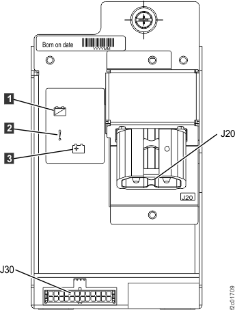
| U242n.mmm.sssssss-Ex-Eyy-E1 | Battery service module, primary | |
| U242n.mmm.sssssss-Ex-Eyy-E1-J30 | Battery service module set signal | |
| U242n.mmm.sssssss-Ex-Eyy-E1-J20 | Battery service module set power (208V) | |
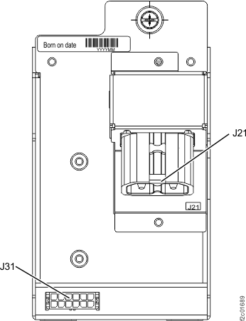
| U242n.mmm.sssssss-Ex-Eyy-E2 U242n.mmm.sssssss-Ex-Eyy-E3 U242n.mmm.sssssss-Ex-Eyy-E4 |
Battery service module, secondary | |
U242n.mmm.sssssss-Ex-Eyy-E2-J31
U242n.mmm.sssssss-Ex-Eyy-E3-J31 U242n.mmm.sssssss-Ex-Eyy-E4-J31 |
Battery service module set signal | |
U242n.mmm.sssssss-Ex-Eyy-E2-J21
U242n.mmm.sssssss-Ex-Eyy-E3-J21 U242n.mmm.sssssss-Ex-Eyy-E4-J21 |
Battery service module set power (208V) |
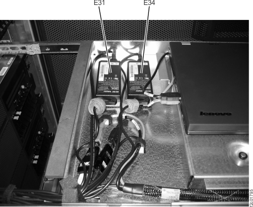
Local remote switch card locations
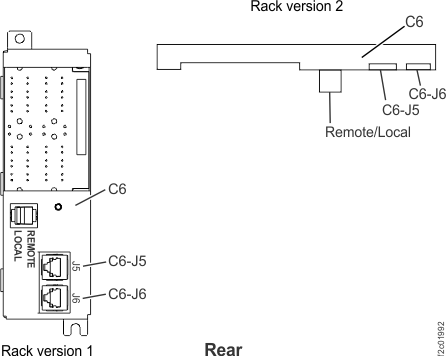
| Location code | Part name | Connector |
|---|---|---|
| U2nnn.mmm.sssssss-C6 | Local remote switch card | |
| U2nnn.mmm.sssssss-C6-J5 | RPC card C1 | |
| U2nnn.mmm.sssssss-C6-J6 | RPC card C2 |
System z local remote switch card locations
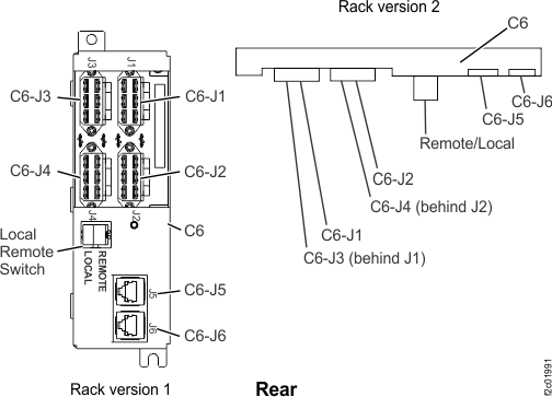
| Location code | Part name | Connector |
|---|---|---|
| U2nnn.mmm.sssssss-C6 | System z local remote switch card | |
| U2nnn.mmm.sssssss-C6-J1 | Customer power control cable | |
| U2nnn.mmm.sssssss-C6-J2 | Customer power control cable | |
| U2nnn.mmm.sssssss-C6-J3 | Customer power control cable | |
| U2nnn.mmm.sssssss-C6-J4 | Customer power control cable | |
| U2nnn.mmm.sssssss-C6-J5 | RPC card C1 | |
| U2nnn.mmm.sssssss-C6-J6 | RPC card C2 |
Rack identity card locations
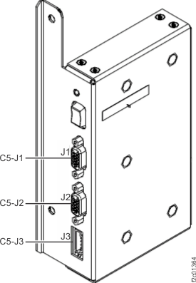
| Location code | Part name | Connector |
|---|---|---|
| U2nnn.mmm.sssssss-C5 | Rack identity card | |
| U2nnn.mmm.sssssss-C5-J1 | To RPC card C1 (Rack 1) To DC-UPS E1 (expansion rack) |
|
| U2nnn.mmm.sssssss-C5-J2 | To RPC card C2 (Rack 1) To DC-UPS E2 (expansion rack) |
|
| U2nnn.mmm.sssssss-C5-J3 | To rack operator panel LEDs (front door of rack) |
RPC card locations
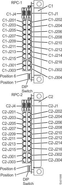
| Location code | Part name | Connector |
|---|---|---|
| U2nnn.mmm.sssssss-C1 | RPC card (upper from rear view) | |
| U2nnn.mmm.sssssss-C2 | RPC card (lower from rear view) | |
| U2nnn.mmm.sssssss-Cx-J1 | Rack-ID card | |
| U2nnn.mmm.sssssss-Cx-J4 | Ethernet tray fans | |
| U2nnn.mmm.sssssss-Cx-J201 | DC-UPS Rack 1 | |
| U2nnn.mmm.sssssss-Cx-J202 | debug | |
| U2nnn.mmm.sssssss-Cx-J203 | DC-UPS Rack 2 | |
| U2nnn.mmm.sssssss-Cx-J204 | Local/Remote card Rack 1 | |
| U2nnn.mmm.sssssss-Cx-J205 | DC-UPS Rack 3 | |
| U2nnn.mmm.sssssss-Cx-J206 | Customer remote rack power control | |
| U2nnn.mmm.sssssss-Cx-J207 | DC-UPS Rack 4 | |
| U2nnn.mmm.sssssss-Cx-J208 | RPC to RPC | |
| U2nnn.mmm.sssssss-Cx-J209 | Not used | |
| U2nnn.mmm.sssssss-Cx-J210 | CEC FSP upper (I2C interface) | |
| U2nnn.mmm.sssssss-Cx-J211 | Not used | |
| U2nnn.mmm.sssssss-Cx-J212 | CEC LPAR upper (serial interface) | |
| U2nnn.mmm.sssssss-Cx-J213 | Not used | |
| U2nnn.mmm.sssssss-Cx-J214 | CEC FSP lower (I2C interface) | |
| U2nnn.mmm.sssssss-Cx-J215 | Not used | |
| U2nnn.mmm.sssssss-Cx-J216 | CEC LPAR lower (serial interface) | |
| U2nnn.mmm.sssssss-Cx-J301 | Not used | |
| U2nnn.mmm.sssssss-Cx-J302 | Not used | |
| U2nnn.mmm.sssssss-Cx-J303 | Not used | |
| U2nnn.mmm.sssssss-Cx-J304 | Not used |
Power distribution units
| Location code | Part name | Connector |
|---|---|---|
| U2nnn.mmm.sssssss-E2x (x = 1 thru 6) |
Power distribution unit | |
| U2nnn.mmm.sssssss-E2x-Jy (y = 1 thru 8) |
208VDC output to CEC enclosure, I/O enclosure, or storage enclosures | |
| U2nnn.mmm.sssssss-E2x-Jy (y = 9, 10) |
208VDC input to PDU |
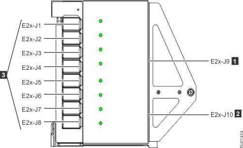
Ethernet switch tray, laptop tray (switches, fans, power junction assembly)
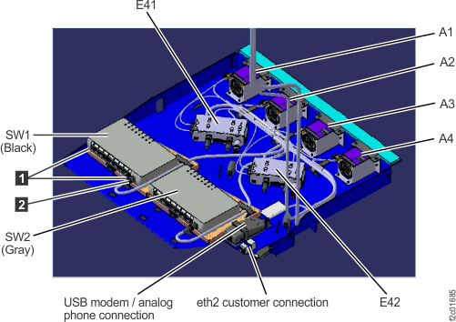
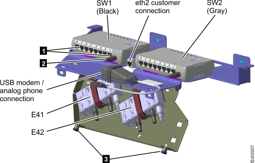
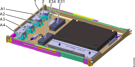
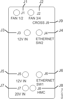
| Location code | Part name | Connector |
|---|---|---|
| U2nnn.mmm.sssssss-Ax (x = 1 thru 4) |
Ethernet switch tray fan | |
| U2nnn.mmm.sssssss-E4x (x = 1, 2) |
Power junction assembly (PJA) | |
| U2nnn.mmm.sssssss-Ex-Jy (y = 1, 2) |
Fan power | |
| U2nnn.mmm.sssssss-Ex-Jy (y = 3, 5) |
12V input from power supply | |
| U2nnn.mmm.sssssss-Ex-Jy (y = 4, 6) |
12V output to Ethernet switches | |
| U2nnn.mmm.sssssss-Ex-J7 | 20V input from power supply | |
| U2nnn.mmm.sssssss-Ex-J8 | 20V out to laptop | |
| U2nnn.mmm.sssssss-Ex-J9 | Fan power to other PJA | |
| U2nnn.mmm.sssssss-SWx (x = 1, 2) |
Ethernet switch |
Power supplies, 20V and 12V for laptop, Ethernet switch tray fans, Ethernet switches