This section contains FRUs that have LED indicators. Each
listed assembly is shown with a description of its LEDs. Do not use
LEDs as a starting point for diagnosing a problem.
I/O enclosure FRUs with LEDs
Table 1. I/O enclosure locations (front)
Part
Reference
I/O enclosure fan
Figure 1
I/O enclosure power supply
Figure 1
Table 2. I/O enclosure locations (rear)
Part
Reference
PCIe and PCN card
Figure 2
Microbay
Figure 3
I/O enclosure device adapter card
Figure 2
I/O enclosure device adapter card, SAS (flash)
Figure 2
I/O enclosure Fibre Channel host card
Figure 2
PCIe storage interface card (applicable for Models 982 and 98F)
Figure 2
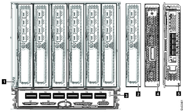
I/O enclosure front
Figure 1. LEDs on the I/O enclosure (front)
Table 3. Interpreting the LEDs on the I/O enclosure (front)
Index
LED Function
Location
Color
LED Off
LED On
LED Flash
1
Identify for I/O enclosure
P1
Blue
Normal
Identify
N/A
2
Identify for I/O enclosure fan
A1, A2
Amber
Normal
N/A
Identify
3
Identify for I/O enclosure power supply
E1, E2
Amber
Normal
N/A
Fast = identify, slow = com fail
4
Output power for I/O enclosure power supply
E1, E2
Green
Standby off
Output on
Standby
5
Input power for I/O enclosure power supply
E1, E2
Green
No input
Input good
N/A
6
Power for I/O enclosure fan
A1, A2
Green
Power off
Power on
N/A
7
Power for I/O enclosure
P1
Green
Power off
Power on
Standby
I/O enclosure rear
Figure 2. I/O enclosure identify LEDs (rear) (models 98x)
Table 4. Interpreting the LEDs on the I/O enclosure (rear)
Index
LED Function
Location
Color
LED Off
LED On
LED Flash
1
Identify for I/O enclosure
P1
Blue
Normal
Identify
N/A
2
Identify for I/O enclosure PCI slot
P1-Cx
Amber
Normal
N/A
Identify
3
Identify for I/O enclosure PCIe and PCN card
P1-C7
Amber
Normal
Fault
Identify
4
Identify for I/O enclosure PCIe storage interface card (Models
982/98F)
P1-Cx
Amber
Normal
N/A
Identify
5
Identify for I/O enclosure device adapter card, SAS (flash)
P1-Cx
Amber
Normal
N/A
Identify
N/A
Power for I/O enclosure PCIe and PCN card (above identify LED)
P1-C7
Green
Power off
Power on
Power standby
Upper LED
Activity for I/O enclosure device adapter card port(Models
980/98B, 981/98E, 984/84E, 985/85E, 986/86E )
P1-Cx-Ty x=3, 6
Green
Not ready1
ready2
N/A
Lower LED
Identify for I/O enclosure device adapter card port(Models
980/98B, 981/98E, 984/84E, 985/85E, 986/86E )
P1-Cx-Ty x=3, 6
Amber
Normal
N/A
Identify
N/A
Fibre Channel host card port LEDs (see Table 5 , Table 6 , Table 7 , and Table 8 )
P1-Cx-Ty x=1, 2, 4, 5
Notes:
LED off indicates port is not ready.
LED on solid indicates port is ready (link is operational).
Fibre Channel host card port LEDs
Table 5 and
Table 6 provide detailed information on Fibre Channel host card port LEDs.
Important: Do not replace host adapter cards based on visual symptoms that are displayed in the
LEDs. Replace them only when they are:
Listed in a serviceable event FRU list, OR
Isolated in an isolation procedure MAP
Note: In the following tables, LED terms are:
Slow flashes are 1 per second
Fast flashes are 4-5 per second
Flashing is very fast flashing; the LED may look dimly lit
Table 5. Fibre Channel host card port LEDs (8 Gb/sec adapters, Normal conditions)
Adapter
Yellow LED
Green LED
State
8-Gb/s adapters
Off
Slow flash
Normal - link is down or not started
2 flashes
On
2-Gb/s link rate - Normal, link is up
3 flashes
On
4-Gb/s link rate - Normal, link is up
4 flashes
On
8-Gb/s link rate - Normal, link is up
Table 6. Fibre Channel host card port LEDs (8 Gb/sec adapters, power-up, failure, download, or test
conditions)
Adapter
Yellow LED
Green LED
State
8-Gb/s adapters
Off
Off
Wake-up failure (dead board)
On
Failure when functioning
On
Off
POST failure (dead board)
On
Failure when functioning
Slow flash
Off
Wake-up failure monitor
Slow flash
Offline for download
Fast flash
Off
POST failure
Slow flash
Restricted offline mode (waiting for restart)
Flashing
Off
POST process in progress
Slow flash
Restricted offline mode (test active)
Table 7. Fibre Channel host card port LEDs (16 Gb/sec adapters, Normal conditions)
Adapter
Upper LED
Lower LED
State
16-Gb/s adapters
Off
On, green
4 Gb/s FC link rate - no I/O
Fast flash, green
4 Gb/s FC link rate - active I/O
On, green
Off
8 Gb/s FC link rate - no I/O
On, green
16 Gb/s FC link rate - no I/O
Fast flash, green
Off
8 Gb/s FC link rate - active I/O
Fast flash, green
16 Gb/s FC link rate - active I/O
Table 8. Fibre Channel host card port LEDs (16 Gb/sec adapters, power-up, failure, download, or test
conditions)
Adapter
Upper LED
Lower LED
State
16-Gb/s adapters
Off
Off
Power off
On, red
Off
POST failure
On, red
Firmware fault
Slow flash, white
Slow flash, white
Power on, firmware not initialized or hardware reset
Slow flash, green
Slow flash, green
Link down
Figure 3. Microbay LEDs
Table 9. Interpreting the LEDs on the microbay
Index
LED Function
Location
Color
LED Off
LED On
LED Flash
1
Microbay power
P1-C7-Cx
Green
Power off
Power on
N/A
2
Microbay identify
P1-C7-Cx
Amber
Normal
N/A
Microbay identify
3
Microbay PCIe link status
P1-C7-Cx-T7
Green
Link bad
Link good
N/A
4
Microbay PCIe port identify
P1-C7-Cx-T7
Amber
Normal
N/A
PCIe port identify
(Not shown)
Flash enclosure service (Purpose is to provide light at the rear of the flash enclosure pair
behind the microbay during service.)
Front of microbay, toward flash enclosure
White
Normal
Service in progress
N/A