Rack power and cooling LED indicators (Models 951, 95E)
This section contains rack power and cooling FRUs that
have LED indicators. Each listed assembly is shown with a description
of its LEDs. Although LED indicators may indicate a failure, they
should not be used as a starting point for a repair.
Rack power and cooling FRUs with LEDs
Table 1. Parts of the rack power and cooling assembly that contain LEDs
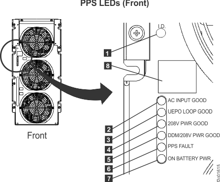
The PPS has
detected an internal error in which case the status display 8 should
be displaying a code and an open serviceable event should
exist.
The PPS cannot
communicate with the other PPS in the
same rack, or the other PPS has an
error.
During a repair of the failing PPS, the
FRU Identify LED 1 is used to determine
the failing PPS.
Both customer mainline power inputs to this rack have been lost
and the PPSs
are using rack battery power to safely shutdown the storage facility.
Indicates one of the following:
PPS firmware is being updated.
PPS PBCM corruption has occurred (call next level of support).
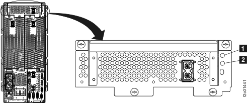
LEDs on the 208VDC power module
Figure 2. LEDs on the 208VDC power module
Table 3. Interpreting LEDs on the 208 VDC power module
Index
LED Function
Color
LED Off
LED On
LED Flash
1
Identify
Amber
Normal
n/a
Identify
2
208VDC
output
Green
PPS
off
Normal
n/a
Amber
Fault
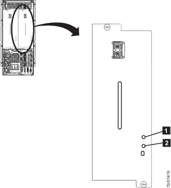
LEDs on the booster power module
Figure 3. LEDs on the booster power module
Table 4. Interpreting LEDs on the booster power module
Index
LED Function
Color
LED Off
LED On
LED Flash
1
Identify
Amber
Normal
n/a
Identify
2
208VDC
output
Green
PPS
off
Normal
n/a
Amber
Fault
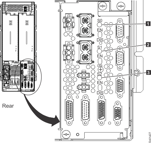
LEDs on the sequencer module
Figure 4. LEDs on the PPS sequencer module
Table 5. Interpreting LEDs on the sequencer module
Index
LED Function
Color
LED Off
LED On
LED Flash
1
Main 208VDC
output
Green
PPS
off
Normal
n/a
Amber
Fault
2
Protected 208
VDC output 0
Green
Normal
Amber
Fault
3
Protected 208
VDC output 1
Green
Normal
Amber
Fault
LEDs on the Power Distribution Unit
Figure 5. Output power indicator (LED) for a power distribution
unit
Table 6. Interpreting LEDs on
the power distribution unit
Index
LED Function
Color
LED Off
LED On
LED Flash
1
Output power
Green
Off1
Normal
n/a
Note 1: Each power output port
is protected by a non-replaceable fuse. If only one output power LED
is off, there is a problem with the power distribution unit.
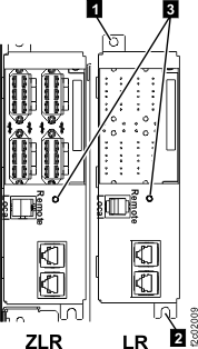
LED on the local remote switch card
Figure 6. Local remote card cables
Table 7. Interpreting LEDs on the
local remote switch card
Index
LED Function
Location
Color
LED Off
LED On
LED Flash
3
Identify
C6
Amber
Normal
N/A
Identify
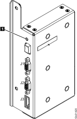
LEDs on the rack identity card
Figure 7. LEDs on the rack identity card
Table 8. Interpreting
LEDs on the rack identity card
Index
LED Function
Location
Color
LED Off
LED On
LED Flash
1
Identify
C5
Amber
Normal
N/A
Identify
LEDs
on the rack operator panel
assembly
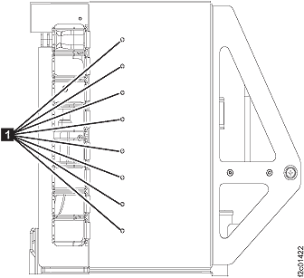
Figure 8. Rack operator panel LEDs on
upper right of rack front cover
Table 9. Interpreting LEDs
on the rack operator panel
assembly
Index
LED Function
Color
LED Off
LED On
LED Flash
1
Line cord 1
Green
1
2
3
2
Line cord 2
Green
1
2
3
3
Identify or System Attention
Amber
Normal
Attention4 (Rack-1
only)
Identify4
Notes:
Off under any of the following conditions:
Customer power is not present
Standby power is present and the Remote Force Power Off is not
active
The corresponding RPC or PPS is fenced
The LED is broken
On solid when PPS DDM power
is on.
Flashes slow (1 flash per 2 seconds) when a PPS is in
Standby, a PPS is
not fenced, or the Remote Force Power Off switch is active. Flashes
rapidly (2 flashes per second) during the PPS power
ON, power OFF, and Force Power OFF sequences.
This LED is used for the following
purposes:
For Rack-1 only:
If the LED is lit solid, it indicates Attention
status, which means that one or more open serviceable events needing
repair exist.
When all serviceable events have been closed
or cancelled, the LED changes to off.
When both attention and
identify status exist on Rack 1, the identify indication is shown
and the LED flashes.
For all racks:
If the LED is flashing, it indicates Identify
status, which means the service representative is replacing a part
that was selected from a serviceable FRU list or from the Parts
Exchange menu option.
Note: Most, but not all, FRUs have identify
indicators. The "light path" identify LEDs are a hierarchy of LEDs
that can identify the rack, enclosure, FRU, and even the FRU connector
for which a cable is connected.
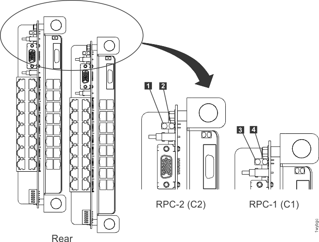
LEDs on the RPC cards
Figure 9. LEDs on the RPC
cards (Models 941, 951)
Table 10. Interpreting LEDs
on the RPC cards
Index
LED Function
Location
Color
LED Off
LED On
LED Flash
1
Operational
C2
Green
fenced, not booted, or no input power
operational
n/a
2
Identify
C2
Amber
Normal
1
Identify
3
Operational
C1
Green
fenced, not booted, or no input power
operational
n/a
4
Identify
C1
Amber
Normal
1
Identify
Notes:
When this LED is on solid, the flash memory in the other RPC card is corrupted.