MES and installation instructions location codes (Models 980, 98B, 981, 98E, 982, 98F)
Physical location codes are used in the MES and installation
instructions. To determine the physical location code for a part,
refer to the appropriate figure:
| Rack | Refer to |
|---|---|
Rack-1, 2 (Models 981, 98E)
|
Figure 1 and Figure 2 (single-phase) Figure 4 and Figure 5 (three-phase) |
Rack-1, 2 (Models 981, 98E)
|
Figure 3
(single-phase) Figure 6 (three-phase) |
Rack-3, 4, 5 (Model 98E)
|
Figure 1 and Figure 2 (single-phase) Figure 4 and Figure 5 (three-phase) |
Rack-1, 2 (Models 980, 98B)
|
Figure 7 and Figure 8 |
Rack-1, 2 (Models 980, 98B)
|
Figure 9 |
Rack-3 (Model 98B)
|
Figure 7 and Figure 8 |
Rack-1, 2 (Models 982, 98F)
|
Figure 10 and Figure 11 |
Rack-1, 2 (Models 982, 98F)
|
Figure 12 |
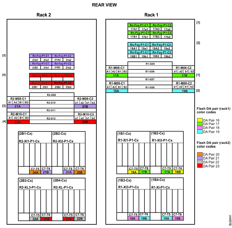
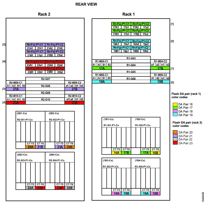
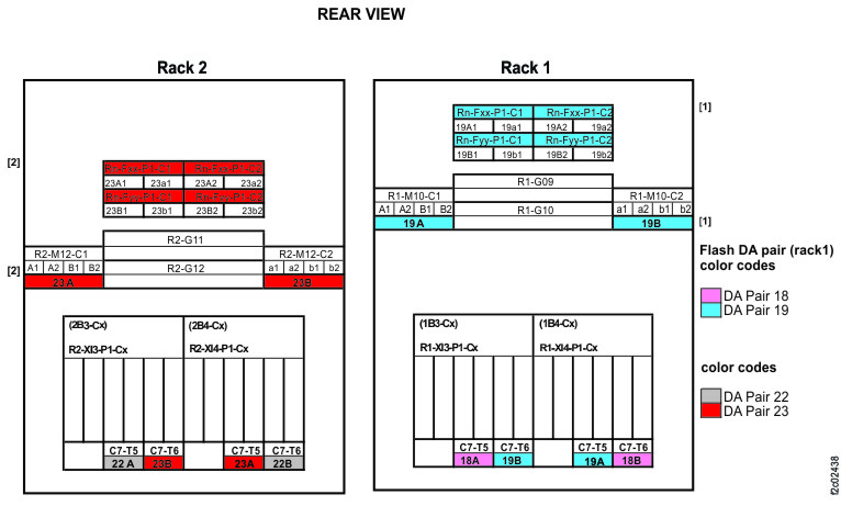
Note: High-performance flash enclosures are in Rack-1 and Rack-2.
Note: High-performance flash enclosures are in Rack-1 and Rack-2.
Notes:
- Only HPFE Gen2 PCIe and SAS details are shown.
- For this model, physical locations are predefined for microbays, but not for HPFE Gen2 flash enclosures.
- Microbays are installed behind a specified storage enclosure pair and take the location code from the lower storage enclosure of that pair. For example, the microbay pair installed behind R1-G06 has location R1-M06.
- The HPFE Gen2 enclosure pair can be located in a different rack than the associated microbay pair.
- The HPFE Gen2 enclosure locations are shown as Rn-Fxx (the upper enclosure of a pair) and Rn-Fyy (the lower enclosure of a pair).
Note: High-performance flash enclosures are in Rack-1 and Rack-2.
Note: High-performance flash enclosures are in Rack-1 and Rack-2.
Notes:
- Only HPFE Gen2 PCIe and SAS details are shown.
- For this model, physical locations are predefined for microbays, but not for HPFE Gen2 flash enclosures.
- Microbays are installed behind a specified storage enclosure pair and take the location code from the lower storage enclosure of that pair. For example, the microbay pair installed behind R1-G06 has location R1-M06.
- The HPFE Gen2 enclosure pair can be located in a different rack than the associated microbay pair.
- The HPFE Gen2 enclosure locations are shown as Rn-Fxx (the upper enclosure of a pair) and Rn-Fyy (the lower enclosure of a pair).
Note: Rack-1 with HPFE (Gen1) is shown on the right. Rack-1 with mix of HPFE (Gen1) and HPFE Gen2,
is shown at the center.