MAP1400 HMC is reporting an installation error before serviceable events being
created
This MAP guides you to repair a problem that was found during the 'Install Storage
Facility' process and continues with the storage facility installation after the problem is
repaired.
Before you begin
CAUTION:
Use this MAP only when you are directed
by the Installation instructions or an on-screen message.
MAP1400 Section-1
Procedure
You are here because a problem occurred during the 'Install
Storage Facility' process. Identify the symptom in Table 1 and follow the listed actions.
Table 1. Symptoms of installation problems
Symptom
Actions
You were sent here by an on-screen message indicating
a MAP1400 Entry Point.
Go to the next step.
You were sent here because a new Serviceable
Event was opened while the 'Field Install Storage Facility' process
was running.
Go to the next step.
The storage facility is listed
on the Storage Facility Install/Remove panel but shows an error condition.
The Field Install Storage Facility process
requires that the managed system is in 'Power Off' state before it starts. You were sent to this
section because it was determined that a managed system belonging to the selected storage facility was found to be in a state other than 'Power
Off'.
Procedure
From the navigation area, click Storage Facility Management > storage
facility > Server View.
View the state of the managed system that was listed in the message that sent you here. Do both
of the managed systems belonging to the storage facility show as 'Powered Off'?
Yes, return to the Install Section and repeat the operation to perform the 'Field Install
Storage Facility'. If the problem persists, contact your next level of support.
No, go to the next step.
Does either of the managed
systems belonging to the storage facility show as 'No Connection'?
Ensure that the Local/Remote switch on the LR/ZLR card is set to Remote.
From the navigation area, click Storage Facility Management > storage
facility.
From the bottom Task area, click Service Utilities > Storage Facility
Power Control. The Power Control window
opens.
Ensure that the Power Control Mode is set to Manual. Click Power OFF Storage
Facility and then click OK.
Allow up to 5 minutes for the storage facility to
power off. Use steps 1 - 3 to verify that the Managed system is now powered off.
Return to the installation process and repeat the operation
to perform the 'Field Install Storage Facility'.
MAP1400 Section-B
About this task
You were sent to this section because the clocks in the managed systems (or storage facility system) for the storage facility require adjustment. The clocks must be
set to Coordinated Universal Time (UTC). The 'File Install Storage Facility'
process fails if the clocks are not within 60 seconds of each other. When you set the clocks,
attempt to set them to be as close as possible (for example, within 5 seconds).
Procedure
Start the ASMI.
From the navigation area,
click Storage Facility Management > storage facility > Server
View > server.
From the bottom Task area, click Operations > Launch Advanced System Management (ASM).
Click OK to confirm the launch of the ASMI. The web browser starts and
the Advanced System Management interface is displayed.
Log in to ASMI with a user ID of admin and a password of
admin2107. If
the login fails, log in as admin with a password of
admin210.
Select System Configuration and then Time Of Day.
Enter the current time in Coordinated Universal
Time (UTC). Click Save Settings.
Click Log out and then close the
web browser.
If necessary, repeat steps 1 - 4 for the other storage
system.
Return to the installation process and repeat the operation
to perform the 'Field Install Storage Facility'.
MAP1400 Section-C
About this task
You
were sent to this section because the configuration file for the storage facility could not be
found. If the storage facility was shipped with an integrated management console, then the
configuration file normally resides on the management console hard-drive. As a backup, and for cases
where a second storage facility is being added to an existing storage complex, the configuration
file is provided on an SDHC memory card in the HMC or CD which is in the ship group. If the
automated process does not find the file on the management console hard drive, then you are asked to
insert the SDHC memory card or CD media.
Procedure
Ensure that the correct SDHC memory card or CD media is inserted and repeat the operation to perform
the 'Field Install Storage Facility'. If you are adding a new storage facility to an existing
storage complex (model 961, 951, 941, or previous models;
adding new storage facility to existing complex does not apply to model 98x), you must do one
of the following steps:
Transfer the SDHC card from the HMC in the new storage facility (MC2) to the HMC in the
existing storage complex (MC1). Ensure that the SDHC card is marked with the serial number of the new
storage facility.
Insert the configuration CD from the new storage facility ship group into the HMC in the
existing storage complex (MC1).
If problems persist, contact your next level of support.
MAP1400 Section-D
About this task
You were sent to this section because the Field Install Storage Facility Verification test
detected an error on one or more of the PCIe
or SPCN buses that interconnect the CEC
enclosures and the I/O enclosures, or the PCN connections between the RPC cards and the I/O
enclosures. A serviceable event is normally logged
for the detected error. Follow this MAP first.
Procedure
If you are installing a Model 983, go to step 6. If not, go to the next step.
Power off the storage facility.
Ensure that the Local/Remote switch on the LR/ZLR card is set to Remote.
From the navigation
area, click HMC Management.
From the navigation area, click Storage Facility Management > storage
facility.
From the bottom Task area, click Service Utilities > Storage Facility
Power Control. The Power Control window
opens.
Ensure that the Power Control Mode is set to Manual. Click Power OFF Storage
Facility and then click OK.
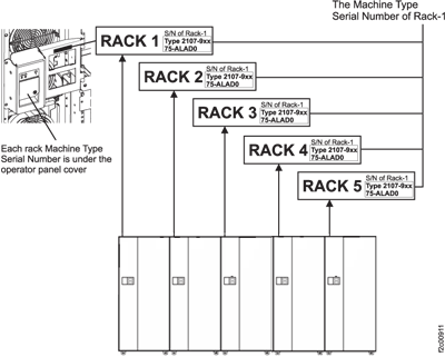
If this installation included multiple storage facility racks, perform a quality check of the
following conditions:
Ensure that the racks were installed in the correct sequence.
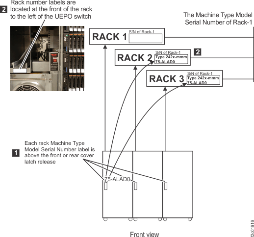
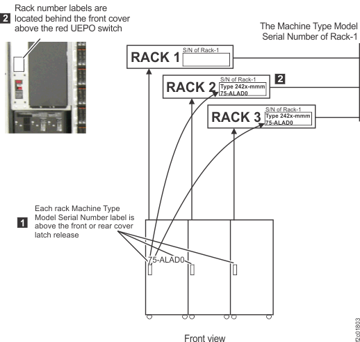
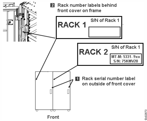
On each expansion rack, check the Rack 1 serial number (S/N) which
appears on a label as shown in the figures below.
Figure 1. Rack serial number and rack number labels (Models 941,
94E)
Figure 2. Rack serial number and rack
number labels (Models 951, 95E)
Figure 3. Rack serial number and rack number labels (Models 961, 96E) (Rack-4 not shown)
Figure 4. Rack serial number and rack number labels (Models 98x,
8xE)
Note: Rack-4 and Rack-5 not shown. Some models do not use a
Rack-3.
If this installation included a single storage facility rack, perform the following check:
Ensure that all PCIe
and PCN (model 98x) or
SPCN (previous models) cables are correctly seated
and have not become dislodged during shipment.
Return to the installation process
and repeat the operation to perform the Field Install Storage Facility.
Note: The storage facility might display an 'Error
state' when starting the Field Install along with a message. This is normal. When you see the
message, click Yes to continue.
Power off the storage facility.
From the navigation area, click HMC Management.
From the navigation area, click Storage Facility Management > storage facility.
From the bottom Task area, click Service Utilities > Storage Facility Power Control. The Power Control window opens.
Ensure that the Power Control Mode is set to Manual. Click Power OFF Storage
Facility and then click OK.
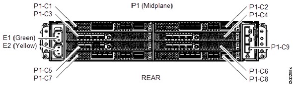
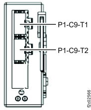
Ensure that the PCN cables are properly connected.
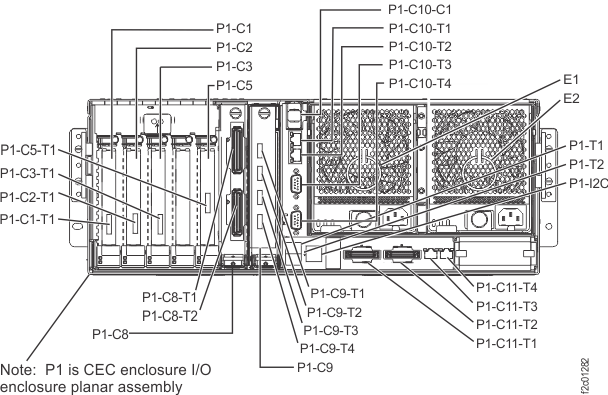
To the I/O enclosure (2U) adapter (PCN), P1-C9. See Figure 5 and Figure 6.
To the management enclosure RPC card Cx-J208. See Figure 7 and Figure 8.
Return to the installation process and repeat the operation to perform the Field Install
Storage Facility.
Note: The storage facility might display an 'Error state' when starting the Field Install along with
a message. This message is normal. When you see the message, click Yes to
continue.
MAP1400 Section-E
About this task
You were sent to this section because the 'Field Install
Storage Facility' process encountered a microcode error.
Procedure
Record any on-screen error messages.
Contact your next level of support.
MAP1400 Section-F
About this task
You were sent to this section because the 'Field Install
Storage Facility' process encountered a microcode error.
Procedure
Record any on-screen error messages.
Contact your next level of support.
MAP1400 Section-G
About this task
You were sent to this section because the 'Field Install Storage Facility' process found
that the storage facility shows an error state. This
is set when the process was run previously and is for information only. This state does not indicate
that the storage facility is still failing.
Procedure
Did you already repair a problem?
Yes, click Yes to continue.
No, repair any outstanding problems.
If the problem persists, then contact your next level of support.
MAP1400 Section-H
About this task
You were sent to this section because the Field Install Storage Facility Verification
process found a mismatch between the resources discovered on the storage facility and those reported in the configuration
file.
Procedure
View and repair any Open Serviceable Events for this storage facility.
If problems were found and repaired, go to the next step to power off the storage facility. Then repeat the operation to perform the
'Field Install Storage Facility'.
If there were no Open Serviceable Events, go to the next step.
Power off the storage facility.
Ensure that the Local/Remote switch on the LR/ZLR card is set to Remote.
From the navigation
area, click HMC Management.
From the navigation area, click Storage Facility Management > storage
facility.
From the bottom Task area, click Service Utilities > Storage Facility
Power Control. The Power Control window
opens.
Ensure that the Power Control Mode is set to Manual. Click Power OFF Storage
Facility and then click OK.
Perform the following checks:
Ensure that you did not add or remove any features before starting
the installation.
Ensure that you loaded the SDHC memory card or CD containing the latest
version of the configuration file.
Ensure that all cables connected during installation are in the
correct locations.
Inspect the storage facility to ensure that no
parts became dislodged during shipment.
Return to the installation process and repeat the operation
to perform the 'Field Install Storage Facility'.
If the problem persists, contact your next level of support.
MAP1400 Section-I
About this task
You were sent to this section because the Field Install Storage
Facility process detected that the system memory or processor resources
discovered do not match the configuration requirement.
Procedure
Record any on-screen error messages.
Contact your next level of support.
MAP1400 Section-J
About this task
You were sent to this section because the 'Field Install Storage Facility' process was
unable to update either the Time Zone or the Time on one or more of the storage facility image LPARs.
Procedure
View and repair any Open Serviceable Events for this storage facility.
If problems were found and repaired, go to the next step.
If there were no open serviceable
events, contact your next level of support.
Power off the storage facility.
Ensure that the Local/Remote switch on the LR/ZLR card is set to Remote.
From the navigation
area, click HMC Management.
From the navigation area, click Storage Facility Management > storage
facility.
From the bottom Task area, click Service Utilities > Storage Facility
Power Control. The Power Control window
opens.
Ensure that the Power Control Mode is set to Manual. Click Power OFF Storage
Facility and then click OK.
Return to the installation process and repeat the operation
to perform the 'Field Install Storage Facility'.
If the problem persists, then contact your next level of support.
MAP1400 Section-K
About this task
You were sent to this section because the 'Field Install Storage Facility' process detected
that the storage facility in not in the correct
Install State to allow the process to continue. The option to perform a Field Install is available
only if the storage facility is in a state of 'Ready
for Field Install' or 'New'.
Procedure
Record the state of the storage facility as
displayed in the Storage Facility Install/Remove panel.
Contact your next level of support.
MAP1400 Section-L
About this task
You were sent to this section because the 'Field Install Storage Facility' process detected
that the 'Service Lock' was already set before the process was started. This indicates that a
Service Action is already in progress for this storage facility.
Procedure
Ensure that all service actions on this storage facility initiated from the management console were completed or canceled.
Ensure that all service actions on this storage facility initiated from an alternative management console were completed or canceled.
Return to the installation process and repeat the operation
to perform the 'Field Install Storage Facility'.
If the problem persists, then contact your next level of support.
MAP1400 Section-M
About this task
You were sent to this section because the Field Install Storage
Facility process could not discover an I/O enclosure.
Procedure
Record any on-screen error messages.
Verify that the PCN cables are properly connected on both the RPC and the I/O enclosure
ends.
Contact your next level of support.
MAP1400 Section-N
About this task
You were sent to this section because one of the following conditions:
The storage facility was not listed on the Install/Add/Remove panel. Selection of this panel
causes the management console to attempt to 'discover' all attached storage facilities. If the new
storage facility is not listed, then it is likely that the management console cannot communicate
with the CEC enclosure service processors in the new storage facility. This problem would be expected only when installing a new
(second) storage facility to an existing storage complex.
One or more CEC enclosure managed systems were found in the
'No Connection' state. If a managed system is in the 'No Connection' state, the management console
cannot communicate with the service processor in that
managed system.
Procedure
If installing a Model 983, go to step 11.
If not, go to the next step.
Allow sufficient time for the service processors to
power on and IML.
Note: The
service processor takes 10 minutes to IML from the time
that power is applied to the CEC enclosure.
Did you wait up to 10 minutes from switching on
(up) the Rack-1 DC-UPS CB1 MAIN LINE SWITCH (Model 98x or
Model 961) or Rack-1 PPS MAIN LINE CB00 (Models before 96x) to apply rack power?
Yes, go to the next step.
No, allow 10 minutes and retry the operation. Return here if you have the same problem.
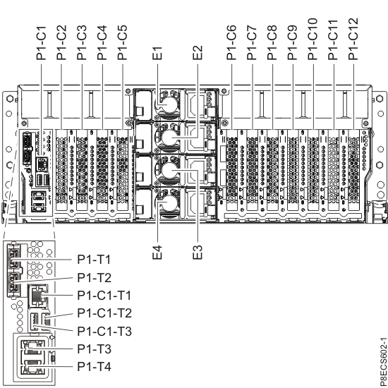
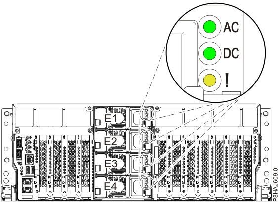
Figure 9. Location codes for the CEC enclosure (rear view) (Models 941,
951)
Note: CEC for models 981, 985, 986 are shown; LEDs and locations
are similar for models 980, 984.
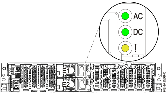
Figure 12. Location of the power supplies and LEDs (Model 982, 988)
Verify that all CEC
enclosures in the storage facility being installed have input
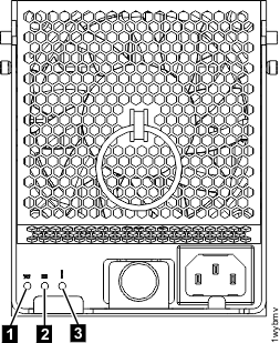
power. Check the LEDs on the rear of the CEC enclosure power supplies.
Note:The power
off state is indicated by the AC or Input power LED
being lit solid and the
DC good (output) LED
flashing. See Figure 11, Figure 12, or Figure 13.
Is the AC
or Input power LED lit
solid on one or more CEC enclosure power supplies in each CEC enclosure (two or more power supplies
for models 981, 982, 985, 986,
988)?
Note: A CEC
enclosure functions normally with only half of the power supplies providing power (models 981, 982, 985, 986, 988: two
of four; other models: one of two). You can wait to repair the failing power supply until after the
SF installation is complete.
Note: For Model 961, ensure shipping brackets were removed and that the power
supplies have been fully inserted into the CEC chassis.
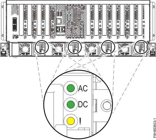
Figure 13. CEC enclosure
power supply LEDs (Model 951 shown, LEDs similar
for Model
961)
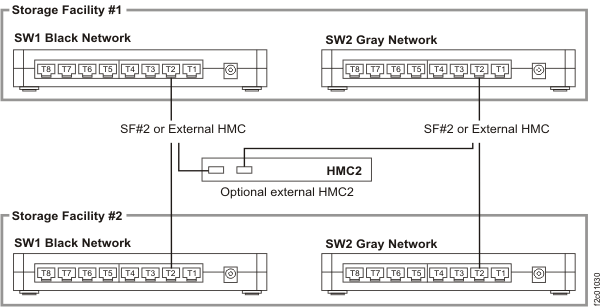
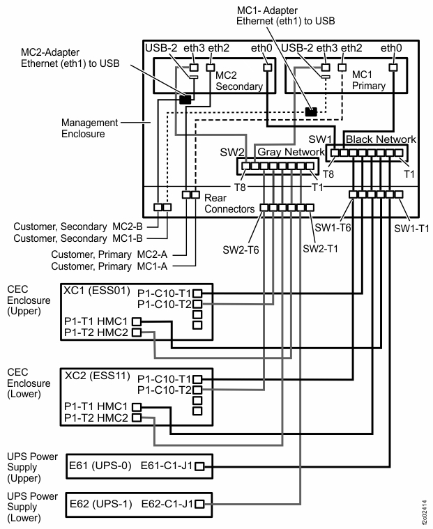
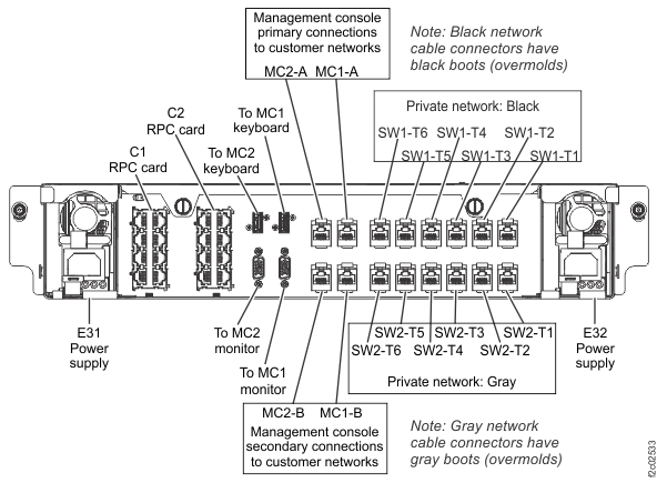
If this is SF2 (the second storage facility in
the storage complex), then verify that the private network cables were installed between SF1 and SF2
Ethernet switches. See Figure 14 and Figure 15.
Note: SF2 does not apply for
model 98x.
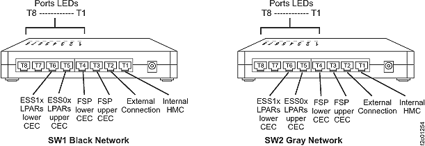
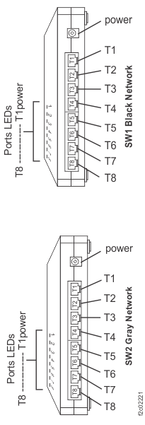
Figure 14. 8-port Ethernet switch port
designations (SW1, SW2-Tx) Model 941, Model 951, and Model 961
Figure 15. Connectivity
between storage facilities for HMC and both 8-port Ethernet switches
Are
the cables connected?
Yes, go to the next step.
No, connect the cables and retry the Install action.
Verify that both the Ethernet switches in the SF being
installed are powered on. Are both Ethernet switches powered on?
Verify that the corresponding link LEDs are lit on the switches for the connections between the
storage
facilities.
See Figure 14 and Figure 15. Are all the expected link LEDs lit?
Yes, go to the next step.
No, swap the Ethernet cable between switches to determine whether the problem is an Ethernet
switch port or cable. Replace the failing FRU and retry the Install action.
For the new storage facility that is being
installed, verify that power is available for the service processor functions in each of the CEC
enclosures.
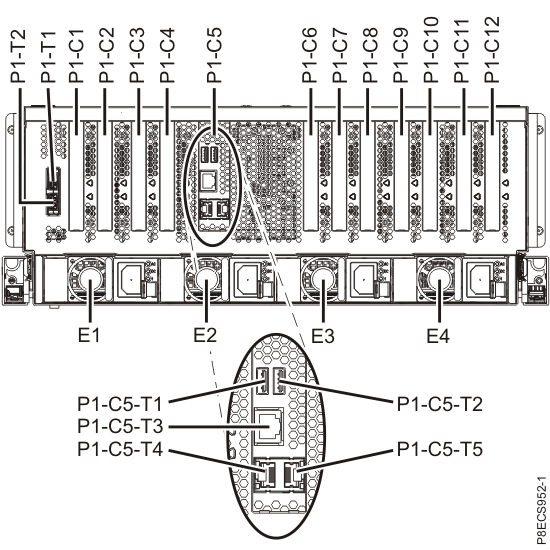
Models 941 and 951: CEC enclosure service processor card P1-C11
Models 982,
988: CEC enclosure service processor card P1-C5
Check the green output power (DC power good) LED of the CEC power supplies (Figure 11, Figure 12, or Figure 13) for each CEC enclosure. Power is available if the LED
is lit solid ("on") or flashing ("standby").
Is power available to both of the service processors?
Identify the failing FRU by doing the following steps:
Move the Ethernet cable to another port on the Ethernet switch and see if the Link LED is now
lit. If the LED is now lit, replace the Ethernet switch. Otherwise, move the cable back to the
original port.
If problem is not the Ethernet switch, remaining FRUs are Ethernet cable or service processor.
Replace the Ethernet cable between the affected service processor
port and the affected Ethernet switch port.
If the failure still occurs, the likely problem is with the service processor. Go to MAP1400 Section-R, which guides you to isolate service processor problems.
Allow sufficient time for the CEC enclosure service processors to power on and IML.
Note: The service processor takes 10 minutes to IML from the time that power is applied to the CEC
enclosure.
Did you wait up to 10 minutes from storage facility UPS powering on?
Yes, go to the next step.
No, allow 10 minutes and retry the operation. Return here if you have the same
problem.
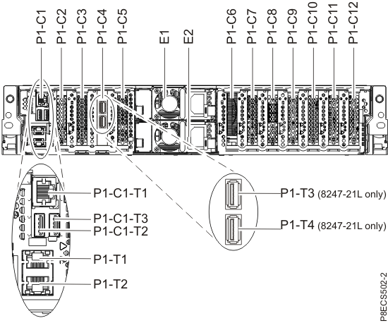
Verify that both CEC enclosures in the storage facility being installed have input power. Check
the LEDs on the rear of the CEC enclosure power supplies E1 and E2. See Figure 20.
Note: The power off state is indicated by the AC being lit solid and the DC good (output) LED
flashing.
Is the AC lit solid on one or both CEC enclosure power supplies in each CEC enclosure?
Note: The
CEC enclosure functions normally with only one power supply providing power. You can wait to repair
the failing power supply until after the SF installation is complete.
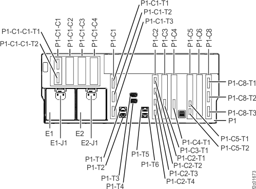
Note 1: CEC ports P1-T1, T2, T3, T4 are labeled "HMC1" or "HMC2".
They are connected to the Ethernet switch, not directly to an HMC.
Identify the failing FRU by doing the following steps:
Move the Ethernet cable to another port on the Ethernet switch and see if the Link LED is now
lit. If the LED is now lit, replace the Ethernet switch. Otherwise, move the cable back to the
original port.
If problem is not the Ethernet switch, remaining FRUs are the Ethernet cables, cable coupler or
CEC enclosure service processor. Replace the Ethernet cable between the affected service processor
port and the affected Ethernet switch port.
If the failure still occurs, the likely problem is with the service processor. Go to MAP1400 Section-R, which guides you to isolate service processor
problem
You were sent to this section because there was no power available on one or both of the
CEC
enclosures.
Procedure
Is the power unavailable on both of the CEC
enclosures?
Yes, go to the next step.
No, ensure that no power cables became dislodged from the failing CEC enclosure during delivery. If no problem is found, then
contact your next level of support.
You were sent to this section because there is a problem with the service processor
function in one of the CEC
enclosures.
Procedure
Normal FRU isolation, parts replacement and verification by using the management console GUI
screens is not available because the logical installation is incomplete.
You must stop this installation and call
the next level of support. They will help you replace the FRU containing
the service processor, then update the VPD and recover the installation
process.
For Model
951, 941, or previous models, the FRU is the CEC enclosure service processor card.
For Models 961, 980, 981, 983, 984, 985, or 986, the FRU is the CEC enclosure system backplane.
For Models 982 or 988, the FRU is the CEC enclosure service
processor card.
MAP1400 Section-S
About this task
You were sent to this section because you found that a new
Serviceable Event was opened while the 'Field Install Storage Facility'
process was running.
CAUTION:
If you Click on the NO button
in answer to the question "Do you want to continue with the Installation
Process?" then the Field Install Storage Facility process terminates.
The automated process must then be run again from the start to complete
the installation.
Procedure
Review the FRU list for each open serviceable
event. Does the FRU list contain FRUs or isolation procedures for
redundant hardware such as:
CEC, I/O, or storage enclosure FRUs including DDMs
Rack power FRUs
Private network FRUs
Informational messages that do not require the installation to
be stopped
Yes, defer the repair until after the installation has been
completed. Return to the Message box and click YES to continue.
No, go to the next step.
Contact your next level of support to determine whether a repair
is needed to allow the 'Field Install Storage Facility' process to complete. Follow the guidance
from support to click YES or NO.
MAP1400 Section-T
About this task
You were sent to this section because the 'Field Install Storage Facility' process detected
a problem in updating the Time Of Day clock on one or both of the managed systems within the storage facility.
Procedure
View and repair any Open Serviceable Events for this storage facility.
If problems were found and repaired, return to the installation process and repeat the
operation to perform the 'Field Install Storage Facility'.
If there were no open serviceable
events, go to
the next step.
Launch the ASMI.
From the navigation area,
click Storage Facility Management > storage facility > Server
View > server.
From the bottom Task area, click Operations > Launch Advanced System Management (ASM).
Click OK to confirm the launch
of the ASMI. The Web browser launches and the Advanced System Management
interface is displayed.
Login to ASMI with a user ID of admin and a password of
admin2107. If
the login fails, log in as admin with a password of
admin210.
Select System Configuration and then Time Of Day.
Enter the current time in Coordinated Universal
Time (UTC). Click Save Settings.
Click Log out and then close the
Web browser.
Were you able to set the Time Of Day clock?
Yes, return to the installation process and repeat the operation
to perform the 'Field Install Storage Facility'.
No, contact your next level of support.
MAP1400 Section-U
About this task
You were sent to this section because the storage facility is listed on the Storage Facility
Install/Remove panel as 'Install Complete'. The 'Install Storage Facility' process
cannot proceed with the storage facility in this
state.
Procedure
Are you performing the first installation of a new storage facility shipped from IBM?
Yes, contact your next level of support for assistance in
establishing the correct storage facility
state.
You were sent to this section because one or more LPARs did not complete IML. Only the
first LPAR in a storage facility image (SFI) is listed
on the screen that sent you here. Both LPARs in the same SFI might be failing.
Determine if each CEC enclosure is in the correct rack position. See Figure 23.
There are two methods to
determine the rack position.
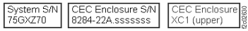
Method one: The serial number of each CEC enclosure is on a label on the front of the CEC
enclosure, compare it to the serial number and location that is listed on the ship group parts list
sheet.
Method two: The CEC enclosure location code is on the rightmost label on the top front of each
CEC enclosure. See Figure 24. Slide the UPS out just
far enough to display the label. The cable ties at the rear must be removed so the cables will not
pull tight and be damaged.
Figure 23. Locations codes for enclosures (Model 983), front
view
Figure 24. CEC enclosure installation labels
Are the CEC enclosures installed in the correct locations in the rack?
Are there any events that are related to the CEC or I/O enclosures?
Yes, go to the next step.
No, for model 961 or 98x, contact your next level of
support.
No, for model 951, 941, or previous models, ensure that the
circuit breakers (CB0 and CB1) on the rear of each battery enclosure were switched on (up position).
The storage facility is shipped with them switched off. If they are in the proper position, call
your next level of support.
Repair the serviceable events and then go to the next step.
Note: If both LPARs in the SFI have failed, the normal repair procedure does not work because the
quiesce/resume process cannot be performed. Contact your next level of support. You might need to power off the storage facility to replace the FRUs and then power it
back on. If power comes up properly, close the serviceable
events and then go to the next step.
Power off the storage facility.
If the storage facility is not a Model 983, ensure that the Local/Remote switch on the LR/ZLR
card is set to Remote.
From the navigation area, click Storage Facility Management > storage
facility.
From the bottom Task area, click Service Utilities > Storage Facility
Power Control. The Power Control window
opens.
Ensure that the Power Control Mode is set to Manual. Click Power OFF Storage
Facility and then click OK.
Exit this MAP and start the installation from the beginning by using the Storage
Facility Install/Remove option (in Storage Facility Management > storage facility).
Display and close all open serviceable events.
Power off the storage facility.
From the navigation area, click Storage Facility Management > storage facility.
From the bottom Task area, click Service Utilities > Storage Facility Power Control. The Power Control window opens.
Ensure that the Power Control Mode is set to Manual. Click Power OFF Storage
Facility and then click OK.
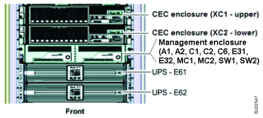
Swap the CEC enclosures into their proper locations (XC1, upper and XC2, lower).
Refer to the original procedures that were used to install the CEC enclosures.
Disconnect the power supply input cables to each CEC enclosure.
Disconnect the remaining cables.
Remove the screws that fasten each CEC enclosure to the rack.
Slide each CEC enclosure fully out and the rails lock into position.
Unlatch each CEC enclosure from the rails, lift it out, and set it safely aside.
Install each CEC enclosure in the proper location. Slide it in and secure it with screws.
Connect all the cables except the power supply input cables.
Connect the power supply input cables.
Start the installation from the beginning by using the Storage Facility
Install/Remove option (in Storage Facility Management > storage facility).
MAP1400 Section-W
About this task
You were sent to this section because the field installation
failed, indicated by the fact that the code failed to set an internal
code power option to "autostart" mode. Both of the CECs need to be
power-cycled to allow finish-setting of the "autostart" mode.
Procedure
Contact your next level of support to report this condition.
Development must determine why the code process failed. The next level of support might direct you
to perform the following general procedures that must be performed before the installation can be
completed:
Power off the storage facility
Wait until the Current State status is "Off"
Power on the storage facility
Verify that the internal code power option is now set to "autostart" mode
Launch the ASMI.
From the navigation area,
click Storage Facility Management > storage facility > Server
View > server.
From the bottom Task area, click Operations > Launch Advanced System Management (ASM).
Click OK to confirm the launch
of the ASMI. The Web browser launches and the Advanced System Management
interface is displayed.
Login to ASMI with a user ID of admin and a password of
admin2107. If
the login fails, log in as admin with a password of
admin210.
What value
is displayed in the field that is labeled "Boot to system service
firmware"?
"Running", go to the next step.
"Standby", do not continue.
Did you previously select the option to certify DDMs?
Yes, the Certify DDMs process was not started by the installation
process. You must manually start it. See MAP1470 Manually start the Certify drives process. After you manually
start the Certify DDMs process, go to the next step.
No, go to step 6.
The Certify DDMs process has been started. When you originally
ran the Certify DDMs process, did you select the option that causes
a call home to occur when the process was to be completed?
Yes, the above procedure reset that code flag, preventing
the call home from occurring. You must manually monitor the progress
of the Certify DDMs process to see when it is complete. Later during
the installation, when you are asked if you selected the call home
option, answer "No" to be guided to manually check the progress and
notify the customer when the process is complete.
The management console Ethernet connection to both UPS is not responding. Possible causes:
This MAP section is only for the condition where the management console cannot communicate to
both UPS through their network card Ethernet connections. If only a single UPS is failing to
communicate this MAP section is not called.
Each UPS network card Ethernet port is pre-configured in manufacturing with a static IP address,
which is used by the management consoles.
The possible causes that a management enclosure could not communicate to both UPS are:
The UPS were installed in the wrong positions in the rack. (The E61 upper UPS only connects to
the black network switch. The E62 lower UPS only connects to the gray network switch.)
The Ethernet cables to both UPS are disconnected.
The Ethernet cables to both UPS are misplugged (cross-connected).
Procedure
Determine if each UPS is in the correct rack position. See Figure 25.
There are two methods to determine the rack
position.
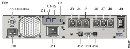
Method one: The serial number of each UPS is on a white label at the rear of the UPS below
connector J7. See Figure 25 and Figure 26. Compare it to the serial number and location
listed on the ship group parts list sheet.
Method two: The UPS location code is on the rightmost label on the top front of each UPS. See
Figure 27. Slide the UPS out just far enough to
display the label. The cable ties at the rear must be removed so the cables will not pull tight and
be damaged.
Figure 25. Locations codes for enclosures (Model 983), front viewFigure 26. Location codes for the UPS (Model 983), rear view
Figure 27. UPS installation labels
Are the UPS installed in the correct locations in the rack?
From the navigation area, click Storage Facility Management > storage facility.
From the bottom Task area, click Service Utilities > Storage Facility Power Control. The Power Control window opens.
Ensure that the Power Control Mode is set to Manual. Click Power OFF Storage
Facility and then click OK.
Shutdown both management consoles.
From the navigation area, click HMC Management.
In the right work area, go to the Operations section and click Shut Down or
Restart. The Shutdown or Restart window opens.
Select Shutdown HMC, then click OK.
Wait for the HMC to power off then go to the next step.
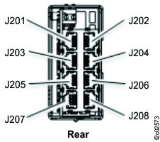
At the rear of the UPS, unplug the input power cable from J10. See Figure 26.
IMPORTANT: Wait up to 5 minutes for the UPS control panel to turn to dark.
Note: The UPS is temporarily powered by the battery until the "On battery" condition
times out.
At the rear of each UPS, ensure that all cables are properly labeled and disconnect them. See
Figure 26.
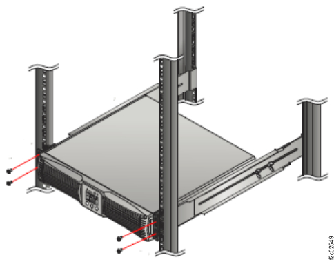
At the front of the rack, remove the four screws and remove each UPS. See Figure 28.
CAUTION:
The combined weight of the UPS with battery exceeds the single-person weight
limit.
Figure 28. UPS front screws
Refer to the UPS installation labels at the top front edge of each UPS and install each UPS in
the correct rack location and secure with screws.
At the rear of the rack, connect all cables, except the power input cable J10, to both UPS. See
Figure 26.
At the rear of the rack, connect the power input cable J10 to both UPS. See Figure 26.
Note: The storage facility and management consoles will automatically power on.
Exit this MAP. Display and close all open serviceable events. Then, start the installation from
the beginning by using the Storage Facility Install/Remove option (in Storage Facility Management > storage facility).
Is an Ethernet cable connected to the C1-J1 connector of both UPS?
See Figure 26.
Yes, go to the next step.
No. Connect the cables. Exit this MAP and retry the storage facility install
option.
All cables to the upper UPS are color coded green. All cables to the lower UPS are color
coded yellow. Are the Ethernet cables cross-connected (swapped) between the upper and
lower UPS?
No. Stop and call the next level of support.
Yes. Properly connect the Ethernet cables. Exit this MAP and retry the storage facility
install option
 being lit solid and the
DC good (output) LED
being lit solid and the
DC good (output) LED  flashing. See Figure 11, Figure 12, or
Figure 13.
flashing. See Figure 11, Figure 12, or
Figure 13.