MAP2470 Powering off and on the storage facility from the management console
Use this MAP for instructions on how to power off and power on a storage facility using the management console.
MAP2470 Section-1 Power off or power on the storage facility
Procedure
- To power off the Model 94x, 95x, 96x, 98x (not 983) storage facility, go to MAP2470 Section-2 Power off the Model 94x, 95x, 96x, 98x (not 983) storage facility.
- To power on the Model 94x, 95x, 96x, 98x (not 983) storage facility, go to MAP2470 Section-3 Power on the Model 94x, 95x, 96x, 98x (not 983) storage facility.
- To power off the Model 983 storage facility, go to MAP2470 Section-4 Power off the storage facility (Model 983).
- To power on the Model 983 storage facility, go to MAP2470 Section-5 Power on the storage facility (Model 983)
MAP2470 Section-2 Power off the Model 94x, 95x, 96x, 98x (not 983) storage facility
Procedure
-
Ensure that the Local/Remote switch that is located on the local remote or System z® local remote switch card is set to
Remote. For Model 941, see Figure 1. For Model
951 or Model 961, see Figure 2.
For Model 98x, see Figure 3.
Figure 1. Local/Remote switch, Model 941 
Figure 2. Local/Remote switch, Models 951, 961 
Figure 3. Local/Remote switch, Models 98x 
- Power off the storage facility.
- From the bottom Task area, click . The Power Control window
opens.
Figure 4. Window: Power Control 
- From the bottom Task area, click . The Power Control window
opens.
- At the rear of
each rack in the storage facility, switch
off the mainline power CB00
 (Figure 5) on both primary power
supplies (PPS).
(Figure 5) on both primary power
supplies (PPS). Figure 5. Rear view of PPS showing CB00 
- Verify that all input power has been removed from each
rack. At the front of both PPSs in each rack, ensure the
 AC INPUT GOOD LED indicator is off.
Note: If the LED is lit, CB00 is not switched off.In Figure 6, the Model 941/94E is shown; the Model 951/95E is similar.
AC INPUT GOOD LED indicator is off.
Note: If the LED is lit, CB00 is not switched off.In Figure 6, the Model 941/94E is shown; the Model 951/95E is similar.Figure 6. LEDs on the PPS (front) 
- At the rear
of each rack in the storage facility, set the main line switch CB1
 (Figure 7) to Off (down) on both DC-UPS.
 Figure 7. DC-UPS DC supply unit (DSU) 
-
Verify that all input power has been removed from each rack. At the rear of both DC=UPSs in
each rack, ensure the
LOCAL AC (input) LED indicator is off. See Figure 7.
Note: If the LED is lit, CB1 is not switched off.
Go to Step 16.
-
For model 98x, single-phase power, at the rear of each rack in the storage facility, set the main line
switch CB1 (Figure 8) to Off (down) on both DC-UPS.
For model 98x, three-phase power, at the rear of each rack in the storage facility, set the main line switch CB1 (Figure 9) to Off (down) on both DC-UPS.
Figure 8. DC-UPS DC supply unit (DSU), Models 98x, single-phase power 
Figure 9. DC-UPS DC supply unit (DSU), Models 98x, three-phase power
Figure 10. LEDs on the DC-UPS DC supply unit (DSU) (Models 98x, single-phase power) 
MAP2470 Section-3 Power on the Model 94x, 95x, 96x, 98x (not 983) storage facility
Procedure
- Observe the front of each rack in the
storage facility. Are the LEDs for AC INPUT GOOD and UEPO LOOP GOOD
 on each PPS lit solid? See Figure 6.
- Yes, go to the next step.
- No. A rack can power on successfully with only one of the
two redundant PPSs operational. However, it is best to have both PPSs
in each rack operational before you power on the storage facility.
Do the following:
- At the rear of the rack, ensure that the mainline power cables are connected to the PPS and also to the customer power source.
- Ensure that the customer circuit breaker for each mainline power cable source is set to on.
- At the rear of each PPS, ensure that each mainline power CB00 is switched to on (up).
- If you cannot find the problem and only one PPS in the rack is not operational, wait and fix it after the storage facility is powered on. There should be an open serviceable event for the problem.
- Observe
the rear of each rack in the storage facility. Is the LOCAL AC (input) LED indicator on each DC-UPS lit solid?
See Figure 7.
- Yes, go to the next step.
- No. A rack can power on successfully with only one of the two redundant DC-UPSs operational.
However, it is best to have both DC-UPSs in each rack operational before you power on the storage
facility. Do the following:
- At the rear of the rack, ensure that the mainline power cables are connected to the DC-UPSs and also to the customer power source.
- Ensure that the customer circuit breaker for each mainline power cable source is set to on.
- At the rear of each DC-UPS, ensure that each main line switch CB1 is switched to on (up).
- If you cannot find the problem and only one DC-UPS in the rack is not operational, wait and fix it after the storage facility is powered on. There should be an open serviceable event for the problem.
- Power on the storage facility.
- From the bottom Task area, click . The Power Control window
opens.
Figure 11. Window: Power Control
- From the bottom Task area, click . The Power Control window
opens.
MAP2470 Section-4 Power off the storage facility (Model 983)
Procedure
-
Power off the storage facility.
-
From the bottom Task area, click . The Power Control window
opens.
Figure 12. Window: Power Control
-
From the bottom Task area, click . The Power Control window
opens.
-
Remove all input power. The UPS will automatically go on battery for up to 5 minutes and then
will power off and the UPS control panel will go dark.
- Unplug the mainline power cables from the UPS from the UPS J10 connectors (lower
left). See Figure 13.
Figure 13. Location codes for the UPS (Model 983), rear view 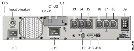
- Unplug the mainline power cables from the UPS from the UPS J10 connectors (lower
left). See Figure 13.
MAP2470 Section-5 Power on the storage facility (Model 983)
Procedure
-
At the front of the rack, locate both UPS (E61 and E62). See Figure 14.
Figure 14. Locations, storage controller enclosures (Model 983) 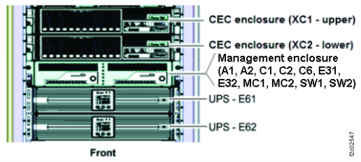
-
Observe the UPS control panel Output status LED indicator. See Figure 15.
Use the following condition that applies.- The indicator is lit on both UPS. Go to step 3.
- The indicator is lit on one UPS and not lit on the other UPS. The storage facility can power
on using one UPS. Go to step 3.Note: The UPS that is not lit can be repaired later by using MAP2870 UPS visual symptoms.
- The indicator is not lit on both UPS. Correct the problem by using MAP2870 UPS visual symptoms. Then return to MAP2470 Section-5 Power on the storage facility (Model 983) step 2.
Figure 15. Locations, UPS control panel (Model 983) 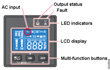
-
Power on the storage facility.
-
From the bottom Task area, click . The Power Control window
opens.
Figure 16. Window: Power Control
-
From the bottom Task area, click . The Power Control window
opens.