MAP2710 Power distribution unit (PDU) isolation (Models 961, 96E)

MAP2710 Section-1

Procedure

  1. You have been sent to this MAP because one or more power supplies (CEC, IO, or storage enclosure) receiving power from a PDU is reporting missing input. This MAP uses visual symptoms to isolate the problem.
  2. If you suspect the power cables that are connected to the PDU are incorrectly connected, refer to Power distribution cables to determine the proper point-to-point cabling for each rack.
  3. At the rear of the rack with the failure, locate the six PDUs (E21 - E26). Figure 1 shows Rack-1. Racks 2, 3, and 4 are similar.
    1. Reference the location codes in the serviceable event FRU list to determine the rack with the failure.
    Figure 1. Base rack locations, front and rear
    Base rack locations, front and rear
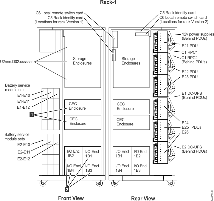
  4. On each PDU, locate the eight output connector green LEDs, one for each output connector. (Figure 2)
    • The upper four output connectors (J1-J4) share power from input connector J9.
    • The lower four output connectors (J5-J8) share power from input connector J10.
    • Each output power connector is protected by an internal fuse that is not repairable.
    • Each output power connector has a green LED that is lit when the fuse is good and output power is present.
    Figure 2. Locations for power distribution unit (PDU) connectors
    Locations for power distribution unit (PDU) connectors
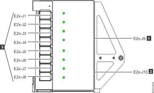
    Attention: If you are here for a high-performance flash enclosure problem that occurred while installing that enclosure (as part of a flash enclosure MES or an expansion rack installation), analyze and repair the problem by finding the condition that applies in Table 1. Later, you use MAP2710 Section-5 PDU and power supply isolation during flash enclosure installation to complete the repair.
  5. Observe the eight green LEDs on each PDU. Find the condition that applies:
    Table 1. LED conditions on each PDU
    If this condition applies: Go to:
    One of the J1-J4 LEDs is not lit; the remaining three LEDs are lit. MAP2710 Section-2 PDU LEDs J1-J4 or J5-J8, one LED is not lit
    One of the J5-J8 LEDs is not lit; the remaining three LEDs are lit.
    J1-J4 LEDs are all not lit. MAP2710 Section-3 PDU LEDs J1-J4 or J5-J8, four LEDs are not lit
    J5-J8 LEDs are all not lit.
    All green LEDs on each PDU are lit. MAP2710 Section-4 PDU LEDs J1-J8 are all lit.

MAP2710 Section-2 PDU LEDs J1-J4 or J5-J8, one LED is not lit

About this task

The PDU output fuse is blown by either an over-current condition in the connected power supply or a short in the interconnect cable.

Procedure

  1. Inspect the interconnect cable from end-to-end for damage.
  2. Verify that the power supply input power LED is off.
  3. Determine the location code of the PDU with the failing port. (Figure 1)
  4. Determine the location code of the power supply that is connected to the failing PDU port. Refer to Location codes.
  5. Display open serviceable events details and one that lists the power supply location code in the FRU list.
  6. The possible failing FRUs are the power supply, the PDU, and the interconnecting power cable.
  7. If the cause of the blown fuse cannot be determined, it is recommended that you replace the power supply and the PDU.
    1. Replace both the power supply and the PDU at one time using the PDU parts exchange procedure.
      Refer to step 9 for more information on starting the repair.
    2. After both the power supply and PDU have been replaced, do a pseudo-repair on the power supply to update enclosure status.
    3. Go to step 10.
  8. If the cause of the blown fuse is known, the power supply or interconnecting cable or both are replaced using the power supply parts exchange procedure. The PDU is replaced using the PDU parts exchange procedure.
  9. If you found the FRU and specific location code in a serviceable event FRU list, use normal serviceable event FRU replace procedures to replace the FRUs. If the FRU was not found in a serviceable event FRU list, use MAP1230 Replace a FRU without using a serviceable event.
  10. Are you here for a high-performance flash enclosure problem that occurred while installing that enclosure?

MAP2710 Section-3 PDU LEDs J1-J4 or J5-J8, four LEDs are not lit

About this task

Four PDU connectors are not receiving common power from the PDU input connector. The PDU input connector receives power from a DC-UPS DSU output connector. The DC-UPS-DSU output connector has a green LED that indicates output power is present.

Procedure

  1. At the rear of the rack, open the PDUs to the service position. Unfasten Callout label 1 and then rotate the upper and lower sets of PDUs away from the rear of the DSUs. (Figure 3)
    Figure 3. Power distribution units in normal position (rack rear view)
    Power distribution units in normal position (rack rear view)
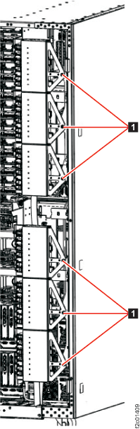
  2. At the top of the DSU, observe the:
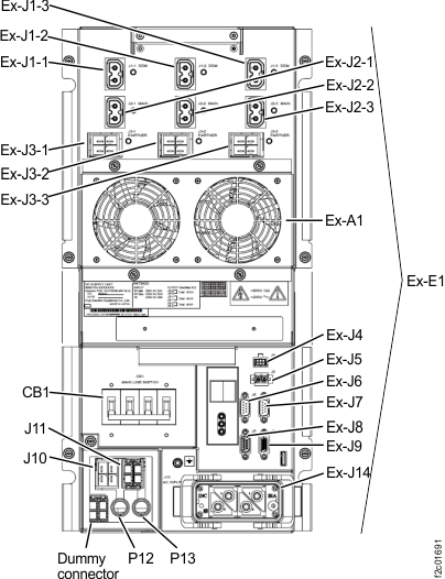
    • Three DDM output LEDs for connectors J1-1, J1-2, J1-3. See Figure 4.
    • Three main output LEDs for connectors J2-1, J2-2, J2-3. See Figure 4.

    Are all six LEDs lit?

    • Yes, go to step 4.
    • No, go to step 3.
    Figure 4. LEDs on the DC Supply Unit (DSU), rear of rack
    Location codes for the DC-UPS (Models 961, 96E) (rear)
  3. A DSU output LED is off. The DSU should detect and report its output error and cause a serviceable event to be opened.
    1. The upper DSU location code is E1. The lower DSU location code is E2.
    2. If the DSU is listed in an open serviceable event FRU list, replace the DSU using standard serviceable event repair procedures.
    3. If the DSU is not listed in an open serviceable event FRU list, replace the DSU using MAP1230 Replace a FRU without using a serviceable event.
  4. All DSU output LEDs are lit. The PDU still has a group of four output LEDs not lit.
    1. If the PDU output LEDs J1-J4 are not lit, ensure the PDU interconnect cable from PDU J9 to the DSU output is properly connected at both ends.
    2. If the PDU output LEDs J5-J8 are not lit, ensure the PDU interconnect cable from PDU J10 to the DSU output is properly connected at both ends.
    3. Were any cables between the DSU and PDUs disconnected or improperly connected?
      • Yes, go to step 5.
      • No, go to step 7.
  5. One or more interconnect cable connections between the DSU and PDUs were found disconnected.
    1. If cable is a point-to-point cable, record the locations of the affected DSU port and PDU port.
    2. If cable is a "Y" cable, record the locations of the affected DSU port and both PDU ports.
    3. Reconnect the cable or cables.
  6. Power should now be restored to the affected power supply units.
    Exit this MAP and do a pseudo-repair of the affected DSU, then close the related serviceable events.
    1. Exit the MAP to return to the screen that sent you here.
    2. To the question, "What was the result of using the service procedure from Infocenter?" click Problem not fixed and then click Next.
    3. To the question, "Did you exchange any parts?" click No and then click Next.
    4. To the question, "Did you isolate the problem,"? click Yes and then click Next.
    5. In the Select all the failing FRUs windows that follow, select the affected DSU for repair.
      1. If the affected DSU appears in the first window, select the DSU, then select All failing FRUs have been selected and click Next.
      2. If the affected DSU does not appear in the first window, select Show more FRUs and click Next. Locate the affected DSU, select it, and click Next.
        Note: If you cannot locate the affected DSU in the Select all the failing FRUs windows, you can select Delay the repair, exit, and use Exchange Parts menu to do the repair: Storage Facility Management > storage facility > Exchange Parts > Exchange Rack Components...
      3. Complete the service action. There is no need to disconnect any cables or remove any parts.
    6. Close the serviceable event that referred you to MAP2710, if it is not already closed.
      • If the cable reconnected in step 5 is a Y cable, there are likely two different serviceable events, one for each of the attached PDUs. Both serviceable events can be closed.
    7. Go to step 11.
  7. The possible failing FRUs are the interconnect cable and the PDU. It is not likely that the DSU output is failing when the output LED is lit. If the interconnect cable is a Y cable and all four power LEDs are not lit on both attached PDUs, go to step 10. Otherwise, continue with the next step.
  8. Replace the affected PDU.After the PDU has been replaced, return here and go to step 9.
    1. If the PDU is listed in an open serviceable event FRU list, replace the PDU using standard serviceable event repair procedures.
    2. If the PDU is not listed in an open serviceable event FRU list, replace the PDU using MAP1230 Replace a FRU without using a serviceable event.
  9. Did replacing the affected PDU resolve the problem?
    • Yes, go to step 11.
    • No, go to step 10.
  10. Replace the interconnect cable. Note which DSU the cable is connected to.
    Exit this MAP and do a pseudo-repair of the affected DSU. When directed to replace the DSU, replace the cable instead.
    1. Exit the MAP to return to the screen that sent you here.
    2. To the question, "What was the result of using the service procedure from Infocenter?" click Problem not fixed and then click Next.
    3. To the question, "Did you exchange any parts?" click No and then click Next.
    4. To the question, "Did you isolate the problem,"? click Yes and then click Next.
    5. In the Select all the failing FRUs windows that follow, select the affected DSU for repair.
      1. If the affected DSU appears in the first window, select the DSU, then select All failing FRUs have been selected and click Next.
      2. If the affected DSU does not appear in the first window, select Show more FRUs and click Next. Locate the affected DSU, select it, and click Next.
        Note: If you cannot locate the affected DSU in the Select all the failing FRUs windows, you can select Delay the repair, exit, and use Exchange Parts menu to do the repair: Storage Facility Management > storage facility > Exchange Parts > Exchange Rack Components...
      3. Complete the service action. There is no need to disconnect any cables or remove any parts.
    6. Close the serviceable event that referred you to MAP2710, if it is not already closed.
      • If the affected interconnect cable is a Y cable, there are likely two different serviceable events, one for each of the attached PDUs. Both serviceable events can be closed.
    7. Go to step 11.
  11. Are you here for a high-performance flash enclosure problem that occurred while installing that enclosure?

MAP2710 Section-4 PDU LEDs J1-J8 are all lit

Procedure

  1. Use the following to continue the repair:
    1. The PDU output LEDs indicate that all output connectors are providing power.
    2. PDU output connectors that are not used for the features present on this rack should have protector covers installed.
    3. All PDU output connectors that do not have protector covers should have cables plugged.
    4. If there is a PDU output connector with no cable and no protector cover, stop and correct this. Look for a cable that is hanging free. These cables have location code labels at both ends that indicate where to plug them. Refer to Power distribution cables to determine the proper point-to-point cabling for each rack.
  2. You were sent to this MAP by a serviceable event FRU list that contained MAP2710 and one or more power supplies.
    1. Using the FRU list location code, find the power supply that is reporting the missing input power. Refer to Location codes in serviceable events to convert location codes to physical locations.
    2. If the power supply input power LED is lit, either the problem is no longer occurring or the power supply has an internal fault and needs to be replaced. If you replace the power supply, use normal serviceable event FRU exchange procedures. Go to step 3.
    3. If the power supply input power LED is lit, and you choose not to replace the power supply but you reconnected the power cable between this power supply and the PDU in step 1, do a pseudo-repair of the power supply.Go to step 3.
    4. If the power supply input power LED is not lit, either the problem is the power supply or the cable to the PDU. Use normal serviceable event FRU exchange procedures to replace the FRUs. Go to step 3.
  3. You are here to do a repair or pseudo-repair of the power supply.
    Note: Use the Help menu to launch a copy of this MAP. Refer to that copy when the repair or pseudo-repair is complete.
    1. Exit the MAP to return to the screen that sent you here.
    2. To the question, "What was the result of using the service procedure from Infocenter?" click Problem not fixed and then click Next.
    3. To the question, "Did you exchange any parts?" click No and then click Next.
    4. To the question, "Did you isolate the problem?" click No and then click Next.
    5. The next FRU in the list is displayed. Repair or pseudo-repair this FRU (the power supply).
    6. Ensure the serviceable event is closed when you are done, then return here and go to step 4.
  4. Are you here for a high-performance flash enclosure problem that occurred while installing that enclosure?

MAP2710 Section-5 PDU and power supply isolation during flash enclosure installation

About this task

You are using MAP2710 to isolate a power problem that occurred while installing a high-performance flash enclosure. You have corrected the problem and will now do a pseudo-repair on one or both power supplies in the enclosure to complete any required firmware updates.

Procedure

  1. Did you do an actual replacement or a pseudo-repair of a power supply in the affected high-performance flash enclosure?
    • Yes, a flash enclosure power supply was replaced. Go to step 2.
    • Yes, a flash enclosure power supply was pseudo-repaired. Go to step 2.
    • No, a flash enclosure power supply was not replaced or pseudo-repaired. Go to step 3.
  2. Do a pseudo-repair of the other power supply in the high-performance flash enclosure. This completes the service action.
  3. Do a pseudo-repair of both power supplies in the high-performance flash enclosure, one at a time. This completes the service action.