MAP2810 Management enclosure reporting I2C interface fault
MAP2810 Section-1
Procedure
MAP2810 Section-2 SRCs BE198D8C, BE198D8D, and BE198D90
Management enclosure power supply interface fault to one RPC card.
About this task
Note:
- BE198D8C, BE198D8D FRUs: MAP2810, RPC card, management enclosure power supply, RPC to power supply cable
- BE198D90 FRUs: MAP2810, RPC card, RPC to power supply cable
Procedure
-
At the front of the rack, slide the management enclosure out to the service position and remove
the top cover.
Note: The management enclosure is below the two CEC enclosures.
- Fully loosen the left and right captive thumb screws.
- Slide the management out fully so the sliding rails lock into place.
- At the rear of the top cover, fully loosen the left and right captive thumb screws.
- Slide the cover back until it lifts off.
Figure 1. Management enclosure (front) 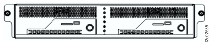
-
Use the serviceable event FRU list location code to determine the RPC card that reports the
error (C1, C2). See Figure 2.
Figure 2. Management enclosure power supply to RPC card cables 
MAP2810 Section-3 SRCs BE198D8E, BE198D8F
Management enclosure power supply reports an interface fault to both RPC cards.
Procedure
-
At the rear of the rack, locate the management enclosure power supply. (E31 left, E32 right)
See Figure 3.
Note: The management enclosure cable management arm partially blocks the rear view.
Figure 3. Locations, management enclosure, rear view 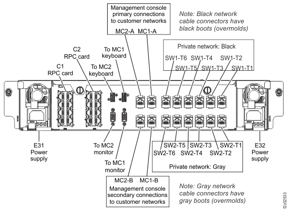
-
Observe the management enclosure power supply rear LEDs. See Figure 4.
Is the input power green LED on?
on?
- Yes, replace the management enclosure power supply. Exit this MAP.
- No, go to step 3.
Figure 4. LEDs, rear of management enclosure power supply 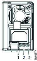
-
Inspect the power cable between the management enclosure power supply and UPS. Ensure that the
cable is firmly seated at both ends. The UPS end does not snap into place. See Figure 3, Figure 5, Figure 6, and Figure 7.
- E31 management enclosure power supply connector J4 power cable connects to E61 (upper) UPS connector J8.
- E32 management enclosure power supply connector J4 power cable connects to E62 (lower) UPS connector J8.
Is the power cable disconnected?Figure 5. UPS to enclosure power supply cables (Model 983) 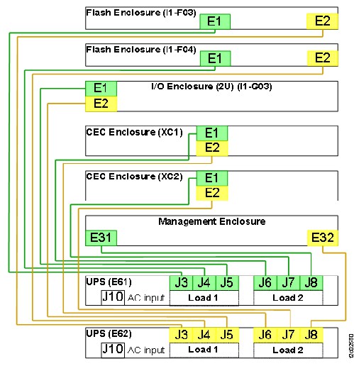
Figure 6. Storage facility power locations 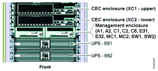
Figure 7. Location codes for the UPS (Model 983), rear view 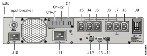
-
Reconnect the power cable. Observe the management enclosure power supply rear LEDs. See Figure 3.
Is the input power green LED on?
- Yes, the problem is repaired. Exit this MAP.
- No, go to step 5.
-
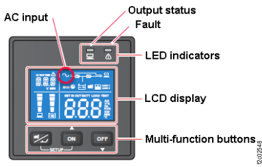
At the front of the rack, observe the UPS control panel that supplies
power to the management enclosure power supply. See Figure 8.
Is the Output status green LED indicator on?- Yes, go to step 6.
- No, the UPS is powered off or failing. Go to MAP2870 UPS visual symptoms. Exit this MAP.
Figure 8. UPS control panel