MAP2850 UPS configuration update failed
This MAP isolates problems that can prevent the management console from starting or completing the UPS configuration update.
MAP2850 Section-1
Procedure
-
At the front of the rack, observe the UPS control panel. See Figure 1 and Figure 2.
Is the Output status green LED lit?- Yes. Go to step 2.
- No, go to MAP2870 UPS visual symptoms.
Figure 1. Locations of storage controller module enclosures (Model 983) 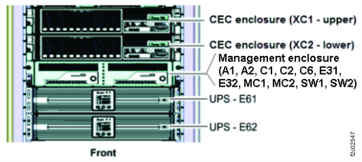
Figure 2. UPS control panel 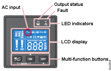
-
At the rear of the rack, observe the UPS network card (E6x-C1). See Figure 3.
Is the Ethernet cable properly connected to the J1 port?- Yes. Go to step 3.
- No. Connect the cable. Exit this MAP and retry the original repair.
Figure 3. Location codes for the UPS (Model 983), rear view 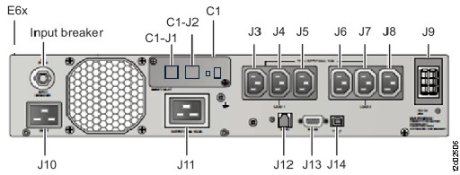
-
Is other end of the Ethernet cable connected to the proper management enclosure rear bulkhead
connecter? See Table 1 and Figure 4.
- Yes. Go to step 4.
- No. Connect the cable. Exit this MAP and retry the original repair.
Table 1. I/O enclosure power cables from UPS UPS UPS Ethernet connector Management enclosure rear bulkhead connector E61 (upper) J1 SW1-T2 (black network) E62 (lower) J1 SW2-T2 (gray network) Figure 4. Ethernet cables (Model 983) 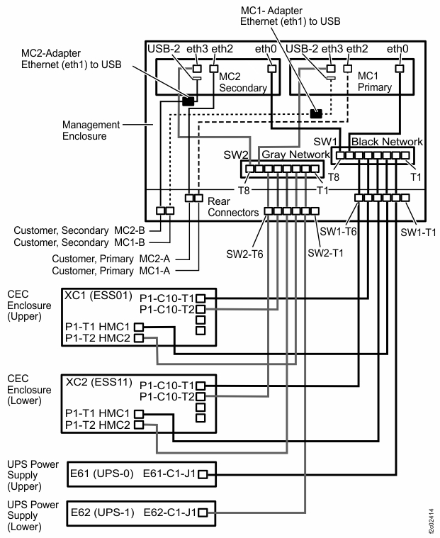
Figure 5. Locations of management enclosure rear bulkhead (Model 983) 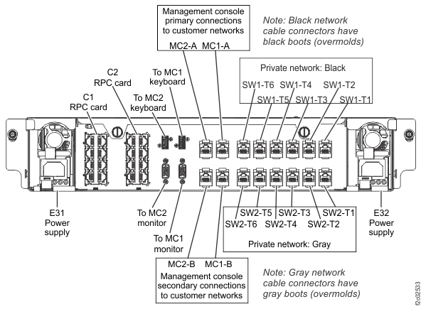
-
Is the UPS network card port green indicator lit or flashing? See Figure 6.
- Yes. The network connection appears to be functional. Exit this MAP and retry the original repair. If that fails, call the next level of support.
- No. Go to step 5.
Figure 6. Locations for the UPS network card (Model 983) 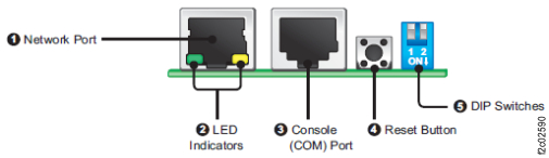
-
Are the UPS network card DIP switches both set to the Off position? See Figure 6 and Figure 7.
Figure 7. DIP switches for the UPS network card (Model 983) 