MAP4810 Resetting the service processor (FSP)
This procedure provides guidance on how to reset the service processor (FSP).
Before you begin
MAP4810 Section-1
Procedure
Are you here to reset the service processor in both
of the CEC enclosures in a storage facility?
- Yes, go to MAP4810 Section-2.
- No, go to MAP4810 Section-3.
MAP4810 Section-2
Note: Use this section only if you are resetting the service processor in both of the CEC enclosures in the storage facility. This is not a concurrent procedure and it will require that the storage facility be completely powered off.
Procedure
-
Verify that the CEC enclosures are already powered off. At the rear of the storage facility, view the CEC enclosure power supplies.
Observe the DC GOOD LEDs
 .
.
- For Models 951 and earlier, see Figure 1.
- For Model 961, see Figure 2.
- For Models 980, 983, 984, see Figure 3.
- For Models 981, 985, 986, see Figure 4.
- For Models 982, 988, see Figure 5.
Are the DC GOOD (output) LEDs lit continuously?- Yes, continue with the next step.
- No, continue with MAP4810 Section-4.
Figure 1. CEC Enclosure Power Supply LEDs (Model 951 shown, LEDs similar for other models) 
Figure 2. CEC enclosure power supply LEDs (Model 961) 
Figure 3. Location of the power supplies and LEDs (Model 980, 983, 984) 
Figure 4. CEC Enclosure Power Supply LEDs (Models 981, 985, 986 ) 
Figure 5. Location of the power supplies and LEDs (Model 982, 988) 
- Power off the storage facility.
- Ensure that the Local/Remote switch on the local remote switch card or System Z local remote switch card is set to Remote.
Figure 6. Service power switch (white, rocker) (Model 941 rear) 
Figure 7. Service power switch (white, rocker) (Models 951, 961 rack version 1) 
Figure 8. Rack identity card (Models 951, 961, rack version 2) 
Figure 9. Local remote switch card, Models 98x (except Model 983) 
Figure 10. Location codes for the rack identity card, Models 98x (except Model 983) Note: The white Service Power Switch is at the top of the assembly, above J1.
Figure 11. Management enclosure locations (Model 983) 
Figure 12. Location codes for the local remote switch card (Model 983) Note: The white Service Power Switch is labeled "On/FPO switch".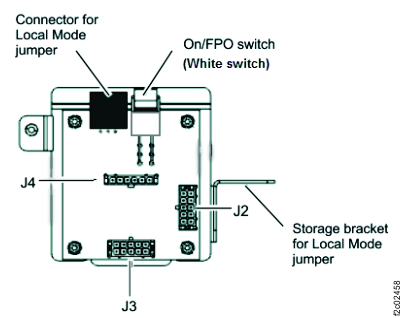
-
Use the white Service Power Switch (see Table 1) to power down the storage
facility. Do the following steps:
-
Set the Local/Remote switch on the local remote switch card or System z® local remote switch
card to Local. See figure references in Table 1.
Table 1. Local/Remote switch and Service Power Switch locations Model Local/Remote switch Service power switch Model 941 Bottom center, Figure 6  , Figure 6
Models 951, 961 rack version 1 , Figure 7 , Figure 7
Model 961 rack version 2 12 , Figure 8  , Figure 8
Models 98x (except 983) Left center, Figure 9 Above J1 , Figure 10 Model 983 C6 , Figure 11 and jumper, Figure 12
Local: Place jumper on connector
Remote: Store jumper on storage bracket"On/FPO switch", Figure 12
-
Set the Local/Remote switch on the local remote switch card or System z® local remote switch
card to Local. See figure references in Table 1.
 .
.MAP4810 Section-3
Note: Use this section if you are resetting the service processor in only one of the CEC enclosures in the storage facility. This must not be done on both of the CEC enclosures in the storage facility or this could result in customer data loss.
Procedure
-
Verify that the CEC enclosure is powered off. At the rear of the storage facility, view the CEC enclosure power supplies
for the CEC enclosure, which houses the service processor that you have been asked to reset. See Figure 13, Figure 14, Figure 15, Figure 16,
or Figure 17.
Are the DC GOOD (output) LEDs lit continuously?
- Yes, continue with the next step.
- No, continue with MAP4810 Section-4.
Figure 13. CEC Enclosure Power Supply LEDs (Model 951) Figure 14. CEC enclosure power supply LEDs (Model 961) Figure 15. Location of the power supplies and LEDs (Model 980, 983, 984)
Figure 16. CEC enclosure power supply LEDs (Models 981, 985, 986 )
Figure 17. Location of the power supplies and LEDs (Model 982, 988) - Pull
the control panel out to the service position.
-
For model 961, at the front of the affected CEC enclosure, press the blue release tab
 to the left and pull the control panel out to the service position. See Figure 18.
When you are finished with this procedure, carefully slide the control panel into the control panel bay until it latches in place.Figure 18. Moving the control panel to the service position 
-
For models 98x, at the front of the affected CEC enclosure, press the blue eject button
E and pull the control panel out to the service position. See Figure 19. When you complete this procedure, carefully slide
the control panel into the control panel bay until it latches in place.
Figure 19. Control panel LEDs 
-
For model 961, at the front of the affected CEC enclosure, press the blue release tab
- Power off the CEC enclosure using the CEC enclosure control
panel. Perform the following steps while referring to Figure 20, Figure 21, or Figure 22.
- Press the Increment button until 02 is displayed on the display.
- Press Enter. Display will show:

- Press Enter. The panel
displays [N<] as shown:

- Press the Increment button.
The panel displays [M<] as shown:

- Press Enter. The panel
displays [V<] as shown:

- Press Enter. The panel
displays [P<] as shown:

- Press Enter. Display will show 02 only.
- Press the Power push-button and hold it until you see the power down sequence start.
- Wait until the CEC enclosure has powered down (Power On light will be flashing).
- Reset the CEC enclosure to Normal
mode.
- Press Enter. Display will show:
- Press Enter. The '<' moves
from [A<] to [N<] as shown:
- Press the Increment button. The
[N<] changes to [M<] as shown:
- Continue with MAP4810 Section-4.
Figure 20. CEC enclosure control panel (Models 941, 951) 
Figure 21. CEC enclosure control panel assembly (Model 961) 
Figure 22. CEC enclosure control panel assembly (Models 98x) 
- Press Enter. Display will show:
MAP4810 Section-4
Use this section to reset the service processor.
Procedure
- Wait while the service processor continues
to IPL. This will take a few minutes. Following a good IPL, the CEC enclosure control
panel will show:
