MAP7060 Replacing the Ethernet switch
MAP7060 Section-1
About this task
Notes:
- The replacement of the Ethernet switch is a manual process. There is no HMC GUI code driven process to manage the resource and help guide you through the repair.
- There are two private networks: one is known as "Gray" and the other as "Black." One of the two networks must always be functional to all connected nodes.
- The private networks are automatically checked every few minutes by a microcode driven "heartbeat" communication process that checks HMC-to-LPAR as well as HMC-to-HMC communications. A serviceable event is opened if a problem is found.
- There is an HMC GUI network topology tool that displays the nodes and their "health" status. Running it does not cause a serviceable event to be created.
Procedure
-
Were you directed to this MAP from a serviceable event FRU list that had MAP7060 as the first
FRU?
- Yes, use the serviceable event FRU location information to determine which Ethernet switch to replace. See figures, then go to step 7.
- No, go to step 3.
Figure 1. "SW1 (left) black" and "SW2 (right) gray" 
Figure 2. 8-port Ethernet switch port locations, Model 98x Note: Upper switch SW1 is "black" network; lower switch SW2 is "gray" network.
MAP7060 Section-2 (16-port switch Model 941)
Procedure
- At the rear of the rack:
- Disconnect the rack power cord
 from the Ethernet switch assembly.
See Figure 3.
from the Ethernet switch assembly.
See Figure 3. - Disconnect the Ethernet cables
 .
. Figure 3. Ethernet switch with cables 
- Disconnect the rack power cord
- Unscrew the two captive thumbscrews , as shown in Figure 4, and remove the Ethernet
switch from the rack.
Figure 4. Ethernet switch (removed) 
- Unplug the power cable
 from the Ethernet switch.
 - Remove the four screws that attach the left and right sheet
metal brackets.
- Install the left and right sheet metal brackets with two
screws each.
- Connect the power cable to the Ethernet switch.
-
At the rear of the rack, install the Ethernet switch assembly in the rack and secure it with
the two captive thumbscrews , as shown in Figure 4.
MAP7060 Section-3 (8-port switch Model 941)
Procedure
- At the rear of the rack:
- Disconnect the rack power cord from the Ethernet switch assembly.
See Figure 5.
- Disconnect the Ethernet cables .
- Remove screw .
Figure 5. 8-port Ethernet switches 
- Disconnect the rack power cord
- Remove the Ethernet switch assembly.
- The Ethernet switch FRU is the assembly that includes the switch, the sheet metal enclosure it is mounted on, and the power adapter inside the enclosure.
- The switch enclosure slides to the rear of the rack to so that you can see the port LED indicators on the top surface of the switch.
- There is one tab at each rear corner of the enclosure
that engages the slots in the sheet metal tray that supports
both switch enclosures. See Figure 6.
- If you do not lift the rear of the switch enclosure, the tabs stay engaged, and the enclosure slides forward to the service position and then stops.
- Instead, if you slide it to the rear a little and then lift the rear of the enclosure, the tabs disengage from the slot, and you can fully remove the enclosure.
Figure 6. Rear enclosure tab and sheet metal tray slot 
MAP7060 Section-4 (8-port Model 951)
Procedure
- At the rear of the rack, remove the air baffle above the Ethernet switch tray, as
shown in Figure 7.
- Remove the two mounting screws .
- Pivot the two mounting tabs inward so they do not interfere with
the cables upon removal.
- Carefully remove the air baffle plate to not damage any cables.
Figure 7. Ethernet switch tray air baffle (Model 951) 
- Remove the two mounting screws
- At the rear of the rack (see Figure 7):
- Disconnect the rack power cord
 from the Ethernet switch assembly.
- Disconnect the Ethernet cables
 .
. - Remove screw
 .
.
- Disconnect the rack power cord
MAP7060 Section-5 (Checking the switch)
Procedure
MAP7060 Section-6 (8-port Model 961)
Procedure
- At the rear of the rack, remove the Ethernet switch (see Figure 8):
- Disconnect the rack power cable and Ethernet cables from the Ethernet switch.
- Do not remove the Ethernet tray sheet metal air baffle .
- The Ethernet switch is held to the sheet metal tray by four hook-and-loop fasteners. See Figure 9.
- Beginning at one corner, lift the Ethernet switch off the tray.
Figure 8. Ethernet switches SW1 and SW2 (Model 961), rack version 1 shown, rack version 2 similar 
Figure 9. Four hook-and-loop fasteners for each Ethernet switch 
- Disconnect the rack power cable
-
For Version 1, do the following steps:
- Remove the two black plastic latches that fasten the new Ethernet switch to the sheet metal bracket. See Figure 10.
- Discard the latches and sheet metal bracket.
- Locate the four hook-and-loop fasteners in the FRU kit and place one squarely on each Ethernet tray hook-and-loop fastener.
- Peel the backing off each hook-and-loop fastener to expose the adhesive surface.
- Align the Ethernet switch with the partner Ethernet switch and push down firmly. Gently lift to ensure that it is properly fastened.
- Properly connect the power and Ethernet cables; refer to the cable location labels.
- Go to MAP7060 Section-5 (Checking the switch).
Figure 10. Release Ethernet switch from the sheet metal bracket 
MAP7060 Section-7 (8-port Model 98x, not 983)
Procedure
- At the right rear of the rack, remove the Ethernet switch:
- Install the new Ethernet switch:
- Hold the switch in position, and position the bracket over the switch.
- Tighten the fasteners to secure the bracket.
- Connect Ethernet cables.
- Connect the input power cable.
- Go to MAP7060 Section-5 (Checking the switch).
Figure 11. 8-port Ethernet switch port locations, Model 98x Note: Upper switch SW1 is "black" network; lower switch SW2 is "gray" network.Figure 12. 8-port Ethernet switch brackets, Model 98x 
MAP7060 Section-8 (8-port Model 983)
Procedure
-
At the front of the rack, slide the management enclosure out to the service position and remove
the top cover. See Figure 13.
Note: The management enclosure is below the two CEC enclosures.
- Fully loosen the left and right captive thumb screws.
- Slide the management out fully so the sliding rails lock into place.
- At the rear of the top cover, fully loosen the left and right captive thumb screws.
- Slide the cover back until it lifts off.
Figure 13. Management enclosure, front (Model 983) 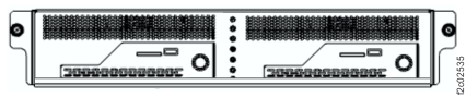
-
Prepare to remove the Ethernet switch:
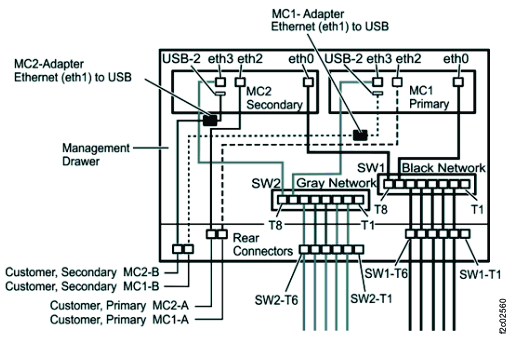
Figure 14. Management enclosure locations. 
-
Remove the Ethernet switch.
Figure 15. Ethernet switch, rear (Model 983) 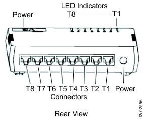
Figure 16. Management enclosure Ethernet cable connections