Installing and testing the Rack-2 I/O enclosures host adapter cards
Procedure
-
Does Rack-2 contain I/O enclosure host adapter cards?
- Yes, go to the next step.
- No. Go to Completing the installation.
- In the left navigation pane, click Storage Facility Management.
- Select the storage facility that contains the Rack-2 host adapters being installed.
- In the right pane lower task area, click MES Install/Remove > Install I/O Enclosures or Components.
- When the "Were you sent here from the MES or installation instructions" screen is displayed, click Yes.
- In the Single Choice Message Box, click Install Host Adapter, then Submit.
-
In the next Single Choice Message Box, click the SFI that the host adapters will be assigned
to, then click Submit.
Figure 1. Location codes for device adapter and host adapter cards 
-
In the Action Panel, select all Rack-2 I/O enclosures (drawers) containing host adapters to be
installed. Valid host adapter locations are slots C1, C2, C4, and C5. See Figure 1 for locations. To select
multiple enclosures, hold the control key and click the enclosures. Click
Submit.
Note: Do not select I/O enclosures that do not contain host adapters to be installed.
- In the Select Empty Slots window, select all the slots that already contain host adapters to be installed. When all slots containing host adapters have been selected, click OK.
-
A series of windows are displayed, including:
- Deactivating application(s)
- Deactivating the system
- Powering off FRU(s)
- The InsMESInstructions window will direct you to return to the installation instructions to install the host adapter to location U1500.xBx.ssssss.P1.Cx. Host adapters are already mechanically installed in the slots indicated in each window. For each window, confirm that the host adapter is securely installed in the slot that is specified in the window, then click Next to continue to the next adapter. After clicking next on the last adapter to be installed, proceed to the next step.
-
A series of windows are displayed, including:
- Powering on FRU(s)
- Waiting 3 minutes for the system to log errors
-
The ConfirmWrapTestBean window opens and asks if you would like to perform
a wrap test on adapter U1500.xBx.ssssss.P1.Cx. It is strongly recommended you perform the wrap tests
at this time. The tests can be run on multiple ports at once, and require one wrap tool per
port.
- To defer the wrap test, click No. You are presented with the same window for each adapter to be installed. Click No for each, then proceed to step 20.
- To continue with the wrap test on the adapter shown, click Yes.
- In the Perform a Wrap Test on Host Ports window, select the ports to test. Make note of the port locations that are selected, as you will be inserting a wrap tool in each port in the next step. Click Start Wrap Test.
- In the Start Wrap Test window, read the directions. After the wrap tool is inserted in each port to be tested, click Start.
- A status window opens that displays the wrap test is in progress.
- When the wrap test for the selected adapter completes, a window opens that displays each port and the result on that port. If additional ports will be tested on the same host adapter, repeat steps 14 - 16 for these additional ports. After all tests are complete on this adapter, click Finish.
- The Wrap Test Complete window opens. Remove the test tools and click Next.
- If an additional host adapter remains to be tested, the ConfirmWrapTestBean window opens for that adapter. Repeat steps 13 - 18 for each additional host adapter.
-
A series of windows are displayed, including:
- Activating Applications
- Verifying Applications
- Waiting 3 minutes for the system to log errors
-
The ServiceActionCompleteForInstallPanelBean window opens and indicates
that the installation is complete. Do not click Next. Customer host cables can be routed at
this time.
Note: Fibre-Channel or FICON cables must have been ordered and received separately by the customer before the following steps can be performed. If the cables are not currently available, you can defer the routing of host cables and continue to step 23.
-
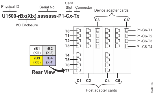
Open the bottom or top tailgate and route the host cables.
- Remove any cover plates as required.
-
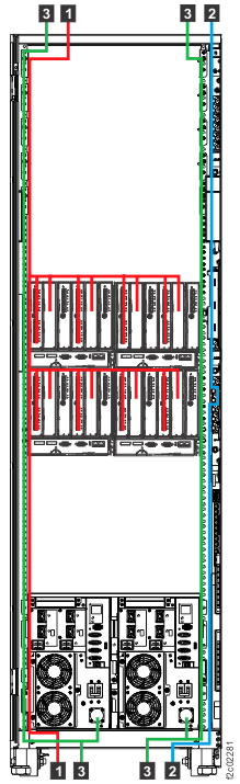
Carefully feed the host cables 1 up or down through the tailgate.
Carefully route the cables along the left side of the rack, across to the destination I/O enclosure
and host card adapter ports, and then plug them in. See Figure 2.
Important: The optical cable plugs (LC connectors) and ports (SFPs) must be cleaned before connecting them. Use cleaning tool 54Y4392 or IBM-approved alternative. After cleaning SFPs with the tool, use air bulb 45D2645 or IBM-approved alternative. For detailed procedures, refer to current DS8000 Info Alerts or contact your next level of support.
Figure 2. Routing customer host, customer network, and power cables, top or bottom Note: Figure shows top or bottom exit routing of host cables 1 , network cables 2 , and power cables 3 .
- Leave some slack in the host cables between the host adapter cards and the tailgate. Use the supplied hook-and-loop fasteners to secure the cables.
- After you route and connect the host cables, replace any cover plates that you removed.
-
Continue to step 23.
Attention: Host adapter ports display as offline until the topology is set by the customer.
- In the ServiceActionCompleteForInstallPanelBean window, click Next and continue with the next section.