Routing and connecting the expansion rack SAS cables
About this task
Procedure
-
Observe the rear of the Model 88E expansion rack you are installing (Rack-2 or Rack-3). Note
which high-performance flash enclosures are present.
Use Table 1, Figure 1, and Figure 2 to determine whether the required device adapter card, SAS (flash) pairs are present or available to install in Rack-1 or Rack-2.
Refer to Figure 4 and Figure 5, if needed.Note: You checked for these adapters in the task Determining whether new and existing racks are compatible.You will now install any adapters that are needed and not already present.
Table 1. Determining whether Rack-1 and Rack-2 contain the necessary DA card, SAS (flash) pairs to support Rack-2 or Rack-3 (Model 88E) high-performance flash enclosures If the new expansion rack has a high-performance flash enclosure in location: (see Figure 1) A DA card, SAS (flash) pair must be present or available for installation in Rack-1 I/O enclosure locations: (see Figure 1 and Figure 2 ) A DA card, SAS (flash) pair must be present or available for installation in Rack-2 I/O enclosure locations: (see Figure 1 and Figure 2) Rack-2: R2-F02 R1-XI1 Slot C3
R1-XI2 Slot C6
(DA pair 8)
Not applicable Rack-2: R2-F04 R1-XI3 Slot C3
R1-XI4 Slot C6
(DA pair 10)
Not applicable Rack-2: Any number of high-performance flash enclosures in locations R2-F05 through R2-F12. No additional interfaces required No additional interfaces required Rack-3: R3-F02 Not applicable R2-XI1 Slot C6
R2-XI2 Slot C3
(DA pair 13)
Rack-3: R3-F04 Not applicable R2-XI3 Slot C6
R2-XI4 Slot C3
(DA pair 15)
Rack-3: R3-F06 Not applicable R2-XI1 Slot C3
R2-XI2 Slot C6
(DA pair 12)
Rack-3: R3-F08 Not applicable R2-XI3 Slot C3
R2-XI4 Slot C6
(DA pair 14)
Rack-3: R3-F10 R1-XI1 Slot C6
R1-XI2 Slot C3
(DA pair 9)
Not applicable Rack-3: R3-F12 R1-XI3 Slot C6
R1-XI4 Slot C3
(DA pair 11)
Not applicable Figure 1. Rack 1-3 storage enclosure and I/O enclosure location codes (Models 988, 88E all-flash) (rear view) 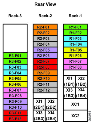
Figure 2. I/O enclosure locations (rear) (models 98x) 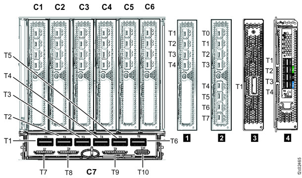
-
Install any adapters that are needed and not already present in Rack-1 or Rack-2. See Table 1, Figure 2, Figure 3, and Figure 4.
-
Slide the card in and the latch the two blue levers 2 .
Figure 3. I/O enclosure adapter retention levers 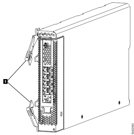
-
Slide the card in and the latch the two blue levers 2 .
-
Determine the destination rack and I/O enclosure for each SAS cable.
- Find the location code label at the free end of each SAS cable.
- Refer to Figure 4 and Figure 5 to translate the destination I/O enclosure location.
Figure 4. Point-to-point cabling diagram for storage enclosure Flash PCIe / SAS cables (Models 988, 88E, rear view, racks 1, 2) 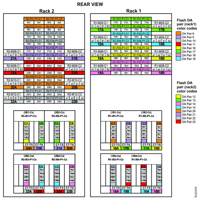
Figure 5. Point-to-point cabling diagram for storage enclosure Flash PCIe / SAS cables (Models 988, 88E, rear view, rack 3) 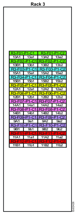
-
Route the SAS cables to the destination rack.
-
Route each cable 1 to the destination rack through the rack to
rack holes at the upper rear of each rack. See and Figure 6 and Figure 7.
Figure 6. Routing remote power control cables and optical cables between racks Note: Models 980 and 98B shown, routing for other models is similar
Figure 7. Routing rack-to-rack power control and optical cables across a rack (earlier model shown, routing for models 98x and 8xE similar) 
-
Route each cable 1 to the destination rack through the rack to
rack holes at the upper rear of each rack. See and Figure 6 and Figure 7.
-
Plug the SAS cables into the connectors on the I/O enclosure device adapter cards as indicated
on the cable labels. Refer to Figure 8 and Figure 9
for connector locations.
Figure 8. I/O enclosure locations (rear)  Note: Enclosures 1B1, 1B2, 2B1, and 2B2 are not present in models 980, 984 (except all-flash), 98B, 84E.
Figure 9. I/O enclosure locations (rear) (models 98x, 8xE)