Section-35, Cable bundle 3, connecting to the lower flash enclosure (I1-F04)
Procedure
-
Connect the green power cable connector to the left power supply (P1-E1). Connect the yellow
power cable connector to the right power supply (P1-E2). See Figure 1.
Secure the power cable behind the power supply retention bracket
 . See Figure 2.
Figure 1. Locations, flash enclosure (I1-F04) 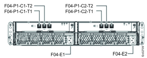
Figure 2. Flash enclosure power cable retention bracket 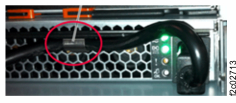
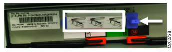
- Remove the disposable covers (white box) for the upper connectors. Do not remove the blue
LNK dust plug (white arrow). See Figure 3.
Figure 3. Protectors for SAS connectors