Section-34, Cable bundle 3, installing cable tie bar at upper flash enclosure I1-F03
Procedure
-
For reference only.
- Figure 1 shows only cable bundle 3 fully installed in the rack.
- Section-47, Table 3 lists the cable groups and cable types.
Figure 1. Cable bundle 3 fully installed 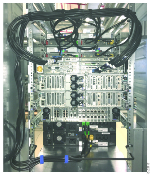
-
At the rear of the rack, install the flash enclosure pair cable tie bar.
-
Install the cable tie bar behind the upper flash enclosure (I1-F3). Use a screw in the top hole
(white arrow) of the rail. See Figure 2.
Note: The yellow arrow is the I/O enclosure cable tie bar.
Figure 2. Upper flash enclosure, cable tie bar, left 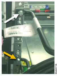
-
Install the cable tie bar behind the upper flash enclosure (I1-F3). Use a screw in the top hole
(white arrow) of the rail. See Figure 2.