Exchange the CEC enclosure memory voltage regulator module
Before you begin
CAUTION:
This assembly contains mechanical moving parts. Use care when
you service this assembly. (C025)
 Use approved ESD procedures to prevent damage.
Attention:
- This procedure is not a stand-alone procedure. Customer disruption and damage to the hardware might occur when microcode and power boundaries are not in the proper conditions for this service action.
- If a serviceable event FRU repair directed you to this procedure, the microcode and power boundaries are already set.
- If a serviceable event FRU repair did not direct you to this procedure, see MAP1230 Replace a FRU without using a serviceable event.
Notes:
- All the cables and FRUs to be removed must be uniquely identified so they can be reinstalled correctly.
- If an installed earthquake resistance kit prevents you from accessing this FRU, refer to MAP1600.
Preparing the CEC enclosure to remove and replace the memory voltage regulator module
Procedure
-
Use the front and rear blue identify LEDs to determine the CEC enclosure to be repaired. Both
blue LEDs should be lit.
- CEC control panel blue identify LED
 as shown
in Figure 1.
as shown
in Figure 1. - CEC enclosure rear blue identify LED
 as shown
in Figure 2.
as shown
in Figure 2.
Note: If both the front and rear CEC enclosure identify LEDs are not lit, use the location code listed in the serviceable event FRU list. See MAP1245 Finding FRUs by using location codes.Figure 1. Control panel LEDs 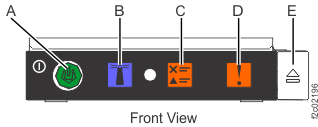
Figure 2. CEC enclosure rear LEDs 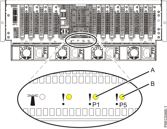
- CEC control panel blue identify LED
-
Verify that the CEC enclosure is in the power-off state. See Figure 3
Figure 3. Location of the power supplies and LEDs (Model 982) 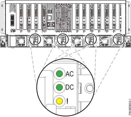
-
Disconnect the power cords from the
CEC with the DC (output) LEDs flashing. See Figure 4.
Notes:
- Ensure the power cords are correctly labeled.
- The power supply LEDs might continue to flash for up to 20 seconds while internal power is discharged.
- The power cord is fastened to the system using the hook-and-loop fastener
 . Unstrap
the fastener to allow the enclosure to be placed in the service position.
. Unstrap
the fastener to allow the enclosure to be placed in the service position.
Figure 4. Removing the power cords (Models 982, 988) 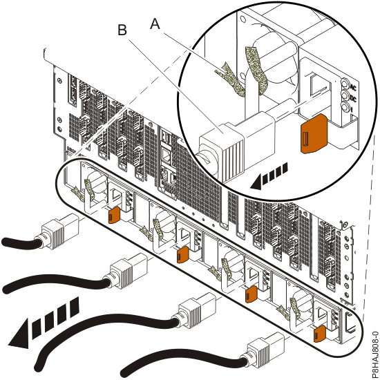
-
Observe the CEC enclosure control panel green power button LED . See
Figure 5.
- If it is off, go to the next step.
- If it is flashing, the CEC enclosure is still in the power-off state. DO NOT CONTINUE. Ensure that you have unplugged the power cables.
Figure 5. Control panel LEDs -
Disconnect all remaining cables from the rear of the CEC enclosure. See Table 1 and Figure 6.
Table 1. CEC enclosure cable connections Connection Description P1-C2-T1, P1-C2-T2 PCIe to I/O enclosures (if C2 present) P1-C3-T1, P1-C3-T2 PCIe to I/O enclosures (if C3 present) P1-C5-T4 (HMC port 1) FSP Ethernet P1-C5-T5 (HMC port 2) FSP Ethernet P1-C6-T1, P1-C6-T2 i2c to RPCs P1-C7-T1, P1-C7-T2 RS485 to RPCs P1-C8-T1, P1-C8-T2 PCIe to I/O enclosures P1-C10-T1, P1-C10-T2 PCIe to I/O enclosures P1-C11-T1, P1-C11-T2 LPAR Ethernet P1-C11-T3, P1-C11-T4 Customer network (optional feature, if used) P1-C12-T1, P1-C12-T2
P1-C12-T3, P1-C12-T4Customer network (optional feature, if used) Figure 6. CEC enclosure location codes (rear view) (Model 982) 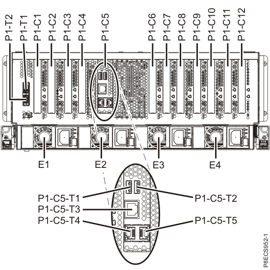
-
Remove the front cover.
CAUTION:A hot surface nearby.
- Ensure that you have the electrostatic discharge (ESD) wrist strap attached. If not, attach it now.
-
Place your fingers on the indentations and pull the latches
located on both sides of the cover.
-
Pull the cover away from the system.
Figure 7. Removing the front cover 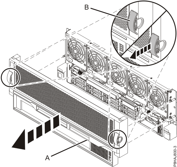
-
Place the CEC enclosure into the service position.
Note:
- When placing the enclosure into the service position, ensure that all stability plates are firmly in position to prevent the rack from toppling.
- Ensure that only one enclosure is in the service position at a time.
- Ensure that the cables at the rear of the system unit do not catch or bind as you pull the system unit forward in the rack.
- When the rails are fully extended, the rail safety latches lock into place. This action prevents the system from being pulled out too far.
- Remove the shipping screws, if they are not removed already.
-
Release the side latches by pressing them downward and then
outward as shown in Figure 8.
-
Slide out the system unit from the rack.
Figure 8. Placing the enclosure in service position 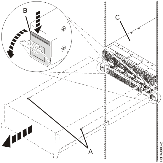
-
Remove the service access cover.
- Ensure that you have the electrostatic discharge (ESD) wrist strap attached. If not, attach it now.
-
Push the release latches in the direction shown.
-
Slide the cover off the system unit. When the front of the
service access cover has cleared the upper frame ledge, lift the cover up and off the system
unit.
Figure 9. Removing the service access cover 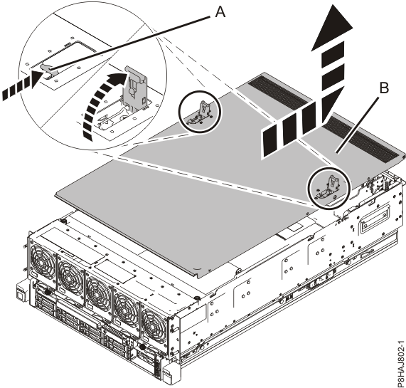
-
Remove the safety cover.
- Ensure that you have the electrostatic discharge (ESD) wrist strap attached. If not, attach it now.
-
Loosen the thumbscrew located at the rear of the cover, by
turning it in the direction shown in Figure 10.
-
Slide the safety cover toward the rear of the system. When the
front of the cover has cleared the upper frame ledge, lift the cover up and off the system.
Figure 10. Removing the safety cover 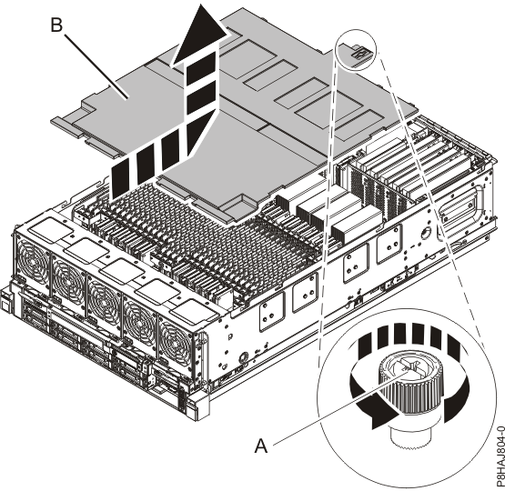
Removing the CEC enclosure memory voltage regulator module
About this task
The system has two memory voltage regulator modules in slots P2-C9 and P2-C42.
To remove the CEC enclosure memory voltage regulator module, complete the following steps:
Procedure
-
Remove the memory voltage regulator module by pulling out the memory voltage regulator module
from the slot by the blue tab while supporting the bottom of the
card. See Figure 11.
Figure 11. Removing the memory voltage regulator module 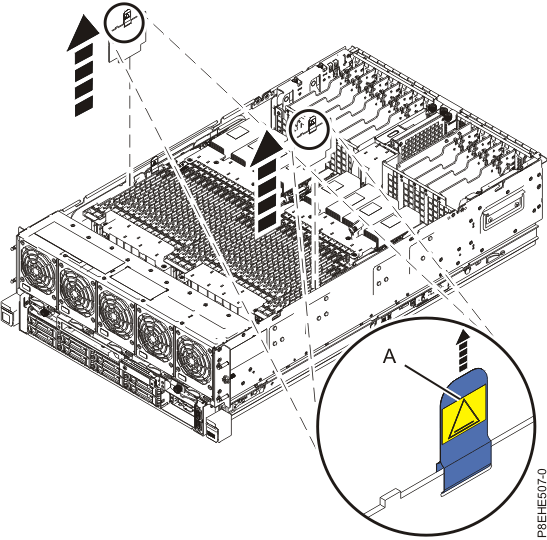
Replacing the CEC enclosure memory voltage regulator module
About this task
To replace the CEC enclosure memory voltage regulator module, complete the following steps:
Procedure
-
Install the voltage regulator module by completing the following steps:
-
Press down the memory voltage regulator module until it is firmly in place.
Note:
- While replacing the memory voltage regulator module, ensure that the green tab
is on the side of the voltage regulator module that is closest to the
front of the system. This check ensures that the orientation of the voltage regulator module in the
system is correct.
- Check for the following events, to identify whether the voltage regulator module is installed backwards:
- When the system is powered on, the system does not go to FSP Standby mode.
- All the CEC fans flash the amber LEDs.
- While replacing the memory voltage regulator module, ensure that the green tab
-
Ensure that the blue tab that extends above the memory voltage
regulator module is moved toward the outside of the frame, and not toward the inside of the frame.
If it is moved toward the inside of the frame, it can touch the adjoining card.
Figure 12. Installing the memory voltage regulator modules 
-
Press down the memory voltage regulator module until it is firmly in place.
Preparing the CEC enclosure for operation after removing and replacing the memory voltage regulator module
About this task
To prepare the system for operation, complete the following steps:
Procedure
-
Replace the safety cover.
-
Push the safety cover toward the chassis.
-
Tighten the thumbscrew by turning it in the direction shown in
Figure 37 to fix the safety cover to the
chassis.
Figure 13. Replacing the safety cover 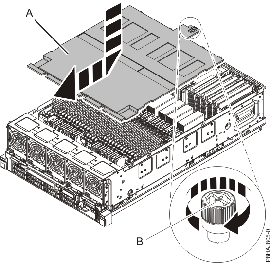
-
Push the safety cover
-
Replace the service access cover.
-
Slide the cover onto the system unit.
-
Close the release latches by pushing them in the direction
shown.
Figure 14. Installing the service access cover 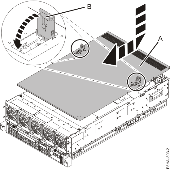
-
Slide the cover
-
Place the CEC enclosure into the operating position.
CAUTION:

Pinch hazard.
-
Unlock the blue rail safety latches by
lifting them upward.
-
Push the system unit back into the rack until both system unit release latches lock into
position.
Note: Slide the system unit slowly into the rack to ensure that your fingers do not get caught in the side rails.
Figure 15. Placing the CEC enclosure into the operating position 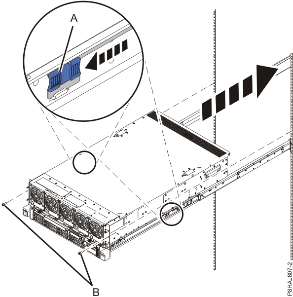
-
Unlock the blue rail safety latches
-
Replace the front cover.
- Ensure that you have the electrostatic discharge (ESD) wrist strap attached. If not, attach it now.
-
Position the cover on the front of the system unit so that the
four pins on the system match the four holes at the rear of the
cover.
-
Press the tabs
 to snap the cover into position.
Figure 16. Installing the front cover 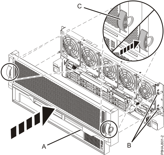
-
Reconnect all cables, except for power cords. See Table 2 and Figure 41.
If optical Ethernet connections are used, use proper cleaning procedures.Important: The optical cable plugs (LC connectors) and ports (SFPs) must be cleaned before connecting them. Use cleaning tool 54Y4392 or IBM-approved alternative. After cleaning SFPs with the tool, use air bulb 45D2645 or IBM-approved alternative. For detailed procedures, refer to current DS8000 Info Alerts or contact your next level of support.
Table 2. CEC enclosure cable connections Connection Description P1-C2-T1, P1-C2-T2 PCIe to I/O enclosures (if C2 present) P1-C3-T1, P1-C3-T2 PCIe to I/O enclosures (if C3 present) P1-C5-T4 (HMC port 1) FSP Ethernet P1-C5-T5 (HMC port 2) FSP Ethernet P1-C6-T1, P1-C6-T2 i2c to RPCs P1-C7-T1, P1-C7-T2 RS485 to RPCs P1-C8-T1, P1-C8-T2 PCIe to I/O enclosures P1-C10-T1, P1-C10-T2 PCIe to I/O enclosures P1-C11-T1, P1-C11-T2 LPAR Ethernet P1-C11-T3, P1-C11-T4 Customer network (optional feature, if used) P1-C12-T1, P1-C12-T2
P1-C12-T3, P1-C12-T4Customer network (optional feature, if used) Figure 17. CEC enclosure location codes (rear view) (Models 982, 988) -
Reconnect the power cords to the
CEC enclosure. See Figure 42.
-
Fasten the power cords to the enclosure using the hook-and-loop fasteners .
Figure 18. Connecting the power cords 
-
Verify that the CEC enclosure has power available. See Figure 43.
Figure 19. Location of the power supplies and LEDs (Model 982, 988) -
Wait up to 5 minutes for the CEC enclosure control panel power-button LED to flash.
See Figure 44.
Note: This ensures the CEC enclosure is in the power-off state.
Is the power-button LED flashing?
- Yes, go to the next step.
- No, ensure the CEC enclosure power supplies are fully seated. The possible failing FRUs are the CEC enclosure system backplane, I2C interface card and cables, and control panel. You can also call the next level of support.
Figure 20. Control panel LEDs