Exchange the UPS to management enclosure power supply cable

Before you begin

CAUTION:
This assembly contains mechanical moving parts. Use care when you service this assembly. (C025)

Icon for electrostatic discharge wrist strapUse approved ESD procedures to prevent damage.

Attention:
  • This procedure is not a stand-alone procedure. Customer disruption and damage to the hardware might occur when microcode and power boundaries are not in the proper conditions for this service action.
  • If a serviceable event FRU repair directed you to this procedure, the microcode and power boundaries are already set.
  • If a serviceable event FRU repair did not direct you to this procedure, see MAP1230 Replace a FRU without using a serviceable event.
Note: All the cables and FRUs to be removed must be uniquely identified so they can be reinstalled correctly.

Remove the UPS to management enclosure power supply cable

Procedure

  1. To locate this FRU, take one of the following actions and then return here and continue to replace the FRU:
    • If this FRU has a FRU identify indicator, use the FRU identify indicator, which is listed in MAP1240 Locating FRUs by using identify indicators. If not, use the location code.
      Note: There might be cases where the FRU failure or fencing conditions prevent the FRU LED indicator from being lit even if the FRU has power.
    • Use the location code, which is listed in MAP1245 Finding FRUs by using location codes.
    • If there is no FRU identify indicator or location code, you were sent here by an isolation MAP or symbolic FRU procedure. Use the information in that procedure and the figures in this procedure to locate the proper part to exchange.
  2. Most, but not all, FRUs have identify indicators. Use the flashing amber or solid blue FRU identify indicators to ensure that you are working on the correct enclosure or FRU.
  3. Read this step completely before going to the next step.
    1. The cable is connected to the rear of the management enclosure, is routed through the cable management arm, and then exits to the connection at the other end.
    2. The cable bundle in the arm might have one or more black plastic zip ties that must be cut to replace the cable.
    3. The new cable being installed must have the same service loop as the other cables at the rear of management enclosure. The service loop prevents the cable from pulling tight when the enclosure is slid in and out.
    4. The management enclosure might need to be slid out and in for different steps in this procedure.
  4. Slide the management enclosure out to the service position. See Figure 1 and Figure 2.
    1. At the front of the rack, fully loosen the left and right captive thumb screws.
    2. Slide the management out fully so the sliding rails lock into place.
    Figure 1. Management enclosure (front)
    Front of Management enclosure (Model 983)
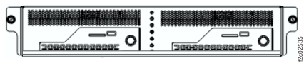
    Figure 2. Storage management module locations (Model 983)
    Storage controller module (enclosures shown)
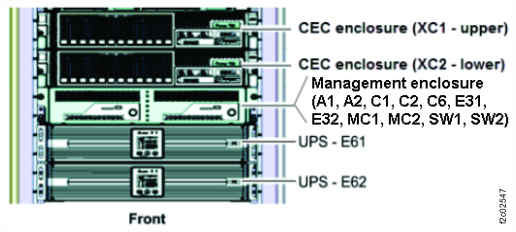
  5. The power cable has the same color code (green or yellow) at both ends. See Table 1 and Figure 3.
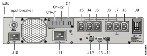
    Table 1. UPS to management enclosure power supply cables (Model 983)
    From UPS port To management enclosure power supply port
    E61-J8 E31
    E62-J8 E32
    Figure 3. UPS to enclosure power supply cables (Model 983)
    UPS to enclosure power supply cables (Model 983)
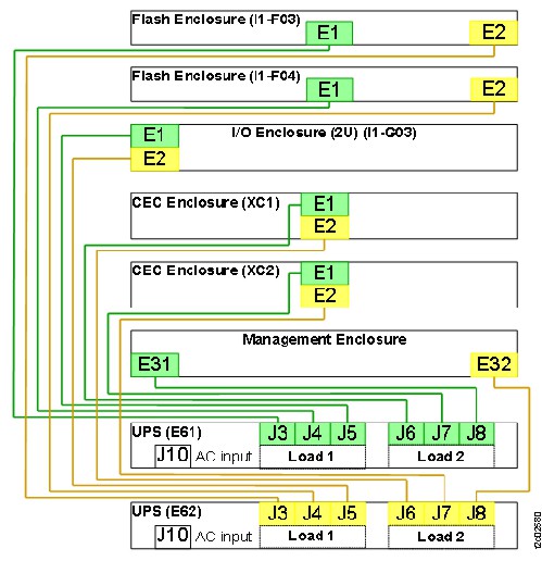
  6. At the rear of the management enclosure, locate the power supply (E31 or E32) that the failing power cable is connected to. See Figure 4 (view from top front of rack) and Figure 5 (view from rear of rack).
    Note: If the power cable is failing, the power supply LEDs are already off. If not, ensure that the correct power supply is being worked with.
    Figure 4. Locations for management enclosure (top view from front) (Model 983)
    Management enclosure locations
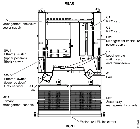
    Figure 5. Locations for management enclosure (rear view) (Model 983)
    Location codes, I/O enclosure (2U) adapter (PCIe, SAS device, zHyperLink)
  7. At the rear of the management enclosure, remove the hook-and-loop fastener from the power supply handle and then disconnect the power cable from the power supply.
  8. Carefully remove the cable from the management enclosure cable management arm.
    1. The cable bundle in the arm might have up to three black zip ties that need to be cut to replace a cable.
    2. Release the hook-and-loop fasteners as needed to remove the cable from the arm.
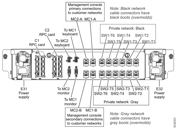
  9. Unfasten and remove the cable down to the UPS connector J8. See Figure 6.
    Note: Photos can be taken to ensure that the new cable is installed with the correct routing and hook-and-loop fasteners positions.
    Figure 6. Locations for UPS (rear view) (Model 983)
    Location codes for the UPS (Model 983), rear view

Install the UPS to management enclosure power supply cable

Procedure

  1. Route the new cable by starting at the management enclosure end.
    1. Connect the cable to the management enclosure power supply.
    2. Fasten the cable to the power supply handle with the hook-and-loop fastener.
    3. Route the cable on the top of the existing cables in the arm.
    4. At the rear of the enclosure, ensure that the power cable has the same service loop as the other cables.
    5. Secure the cables to the arm with the existing hook-and-loop fasteners.
  2. Route, secure, and connect the cable to the UPS.
  3. Fasten the cable to the UPS cable retention bar by using the hook-and-loop fastener.
  4. Test the service loop for all the cables in the cable management arm. Carefully slide the enclosure slowly in and out, checking that none of the cables pulls tight.
  5. Ensure that the enclosure is in the operating position with the left and right captive thumb screws fastened.
  6. Exit this service information center parts exchange procedure and return to the procedure that sent you here.