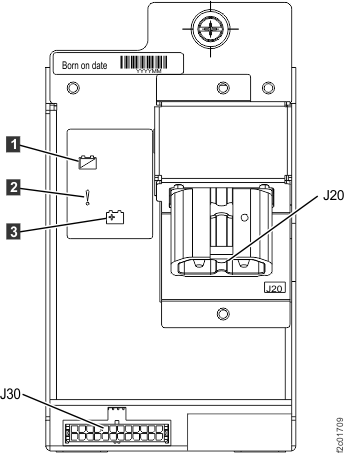
MAP1240 Locating FRUs by using identify indicators
About this task
The primary method to locate a FRU to be exchanged is
by using the hierarchy of identify indicators for that FRU. When the
FRU to be exchanged has been selected in a serviceable event, or selected
using the FRU replace options, the management console causes the hierarchy
of identify indicators to be lit.
For example, if you select
to exchange a storage enclosure DDM FRU from a serviceable event,
the following identify indicators are lit:
Rack identify indicator (on the rack operator panel) for the rack
that contains the FRU
Storage enclosure identify indicator for the enclosure that contains
the FRU
DDM identify indicator for the specific DDM that is to be replaced
For those FRUs that do not have an identify
indicator (see Table 1, Table 2, Table 3),
the rack and enclosure identify indicators are still lit. To determine
the actual FRU within the enclosure, you need to use the last part
of the location code for that FRU. See MAP1245 Finding FRUs by using location codes
For Rack-1 Model 951, 961 , 98x (except 983), see
Figure 2.
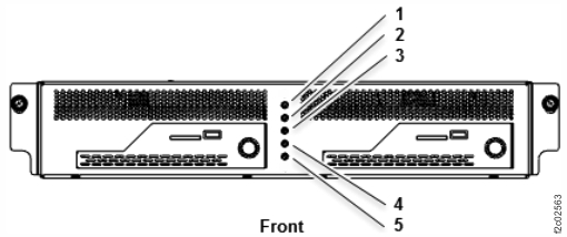
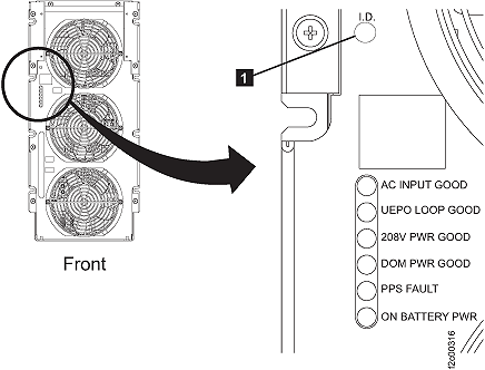
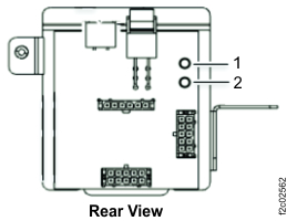
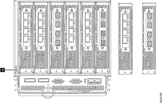
For Model 983, the system identify LED is located on the management
enclosure front panel. See Figure 3.
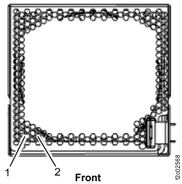
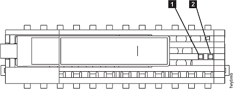
Figure 1. Model 941 "Identify" indicator
(LED) on a rack operator panel
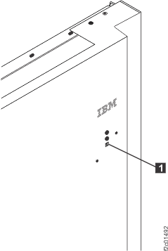
Figure 2. Model 951, 961 "Identify"
indicator (LED) on the upper right of the front cover
Note: Model 98x front door LEDs are similar, but are located on the
left side of the front door.
Figure 3. Model 983 management enclosure front panel
For all models except 983, the FRU is in the rack with the operator panel identify LED
flashing. Go to step 5.
For model 983, there is no rack operator panel or rack identify LED. Instead, the system identify LED
illuminates on the management enclosure. Use enclosure identify and FRU identifiy LEDs
to locate the FRU. Go to step 5.
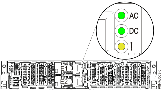
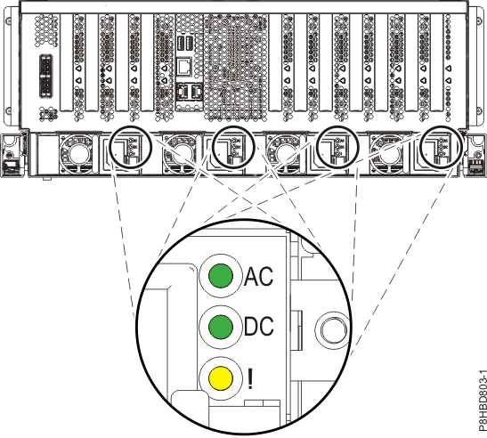
The FRU identify LED indicator
that you attempt to find in the following steps might not be lit under
these circumstances:
The LED is burnt out.
The FRU that contains the LED is no longer able to control the
LED.
The LED might be controlled by a different FRU that feeds a signal directly or by a cable to the
FRU to be identified. The controlling FRU or the cable might have a problem.
If the FRU identify LED indicator is not operational, use the
location code to determine the failing FRU.
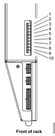
Open the front and rear covers of the rack containing the
FRU determined in the above steps.
You can now locate the area of the rack containing the
FRU.
Use the FRU description and FRU location code from a
serviceable event FRU list or the exchange FRU option to find the
area of the rack containing the FRU:
The
MTMS (machine type model serial number) is the first part of the FRU
location code. Example: Location
code = U2424.941.75ABCD0-C2 where U2424.941.75ABCD0 = MTMS and C2
= FRU location within the MTMS.
Note: If a FRU is contained
in an enclosure, only the enclosure is listed below. If the FRU is
not contained in an enclosure, then it is listed in the table.
Table 1. Model 941, 94E FRU identify LED locations
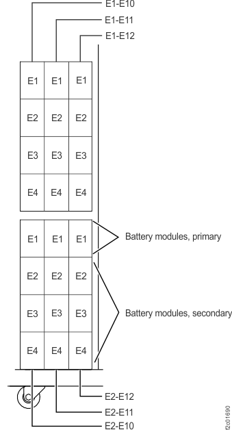
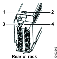
At the rear of the rack, find the battery enclosure with the flashing identify LED .
Figure 4. All models battery module enclosure locations (rear)
Figure 5. All models battery module set locations (front)
MAP1240 Section-3 (DC-UPS battery service module set)
Procedure
At the front of the rack, find the primary battery service module (Ey-Exx-E1) with the flashing
fault/identify LED .
Figure 6. Battery service module, primary, locations (front)
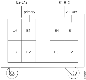
Figure 7. Battery service module (BSM) set locations (Models 961, 96E)
(front)
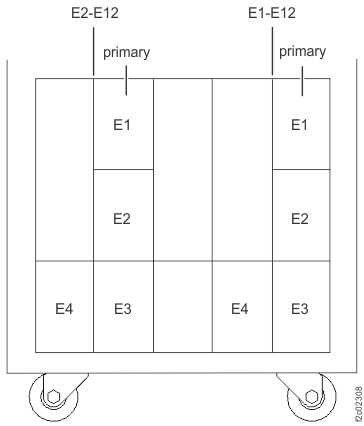
Figure 8. Battery service module (BSM) set locations (Models 98x,
8xE single-phase power) (front)Figure 9. Battery service module (BSM) set locations (Models 98x,
8xE three-phase power) (front)
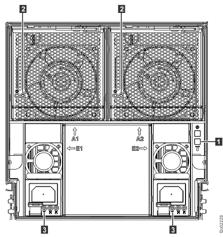
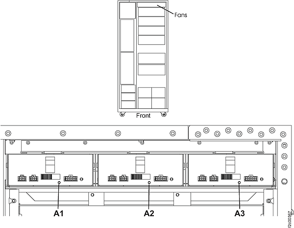
MAP1240 Section-4 (DASD fan tray)
Procedure
1. At the front of the rack, find the DASD fan tray with the flashing identify LED [A1] [A2]
[A3].
Figure 10. Models 92x, 93x, 92E, 9A2, 9B2, 9AE, 941 "Identify" indicator (LED) for a DASD fan
tray
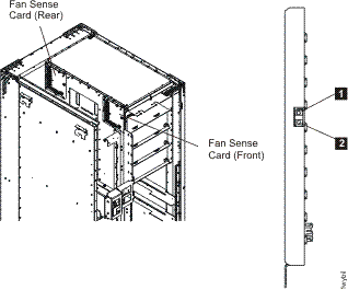
MAP1240 Section-5 (fan sense card)
Procedure
1. At the front and rear of the rack, find the fan sense card with the flashing identify LED
.
C3 location is at the front of the rack
C4 location is at the rear of the rack
Figure 11. Models 92x, 93x, 9A2, 9B2, 941 LEDs on the fan sense cards
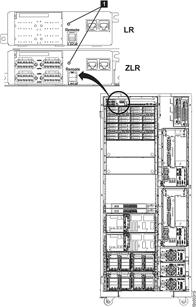
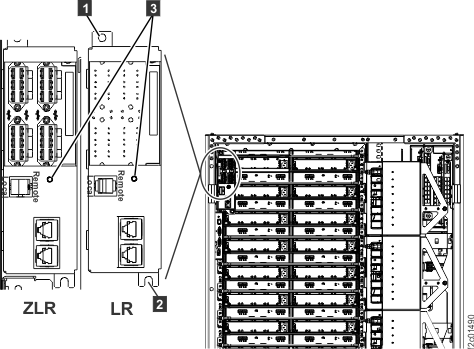
MAP1240 Section-6 (local remote or zSeries local
remote switch card)
Procedure
At the rear of the rack, find the local remote switch card or zSeries local remote switch with the
flashing identify LED (Figure 12) or LED
(Figure 13).
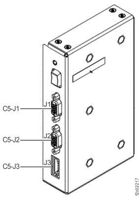
Figure 12. Model 941 "Identify" indicators (LEDs) for local remote and zSeries local remote switch
cards
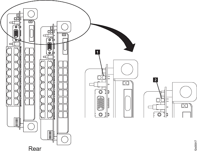
Figure 13. Model 951, 961 "Identify" indicators (LEDs) for local remote and
zSeries local remote switch cards
Note: Model 98x local remote switch card identify LED is similar;
the card is located at right rear of rack.
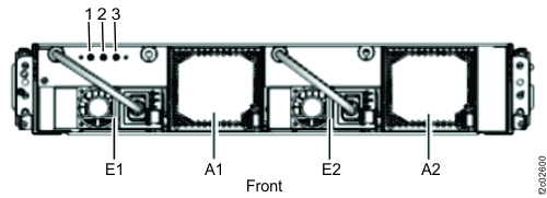
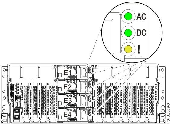
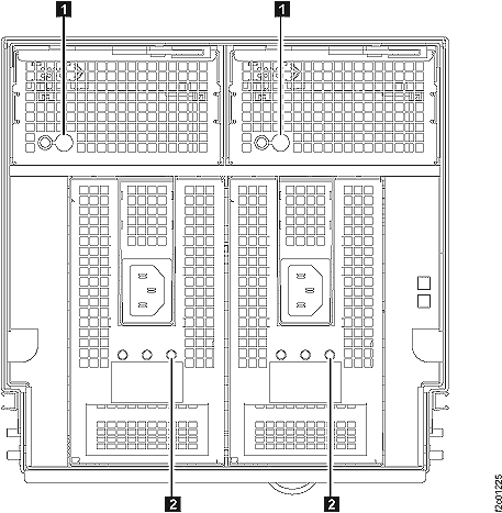
MAP1240 Section-7 (primary power supply, PPS)
Procedure
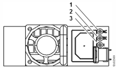
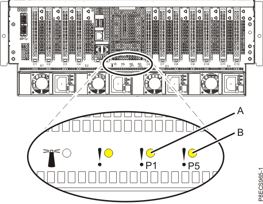
At the front of the rack, find the primary power supply with the flashing identify LED .
E1 location is upper PPS
E2 location is lower PPS
Figure 14. All models "Identify" indicator (LED) for a PPS
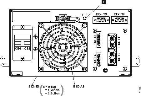
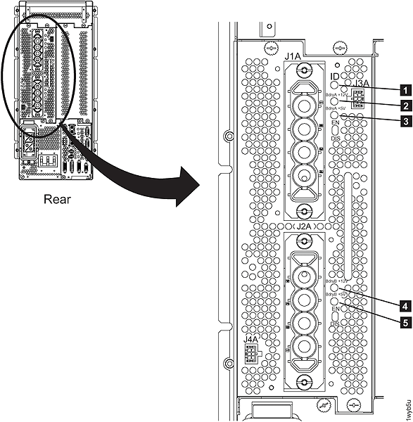
The Models 941, 94E 5/12V DDM
power module identify LED is at the rear of the rack.
Figure 15. "Identify" indicator (LED) for a 5/12V DDM power module
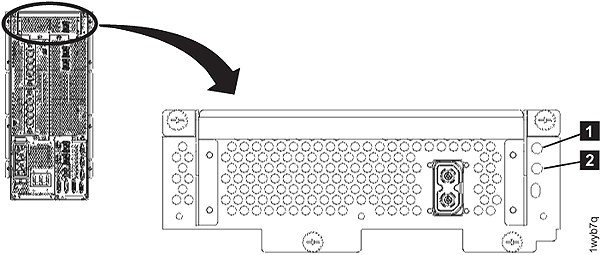
The booster power module identify
LED is at the rear of the rack.
Figure 16. All models "Identify" indicator (LED) for a booster power module
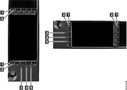
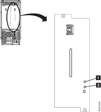
The Models 951, 95E 208V DDM power module
identify LED is at the rear of the rack.
Figure 17. "Identify" indicator (LED) for a 208V DDM power module
MAP1240 Section-8 (DC-UPS DC supply unit)
Procedure
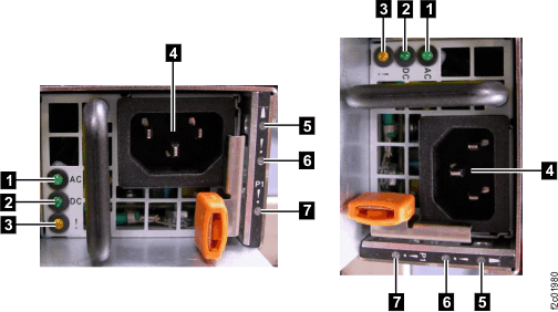
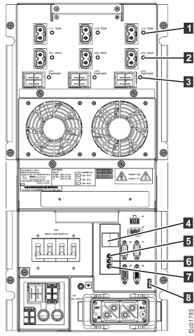
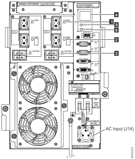
At the rear of the rack, find the DC-UPS DSU with the flashing DSU service LED .
Figure 18. LEDs on the DC-UPS DC Supply Unit (DSU) (Models 961,
96E, 98x, 8xE three-phase), rear
of rack
Figure 19. LEDs on the DC-UPS DC Supply Unit (DSU) (Models 98x,
8xE single-phase), rear of rack
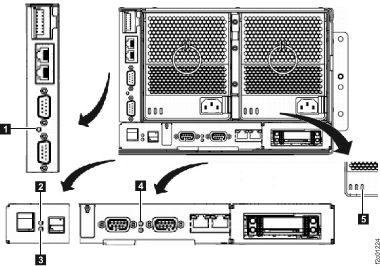
MAP1240 Section-9 (rack identity card)
Procedure
1. At the rear of the rack, observe the identify LED .
Figure 20. Model 941 "Identify" indicator (LED) on the rack identity card
Figure 21. Models 951, 95E "Identify"
indicator (LED) on the rack identity card
Figure 22. Location codes for the rack identity card
Note: Identify LED is located at top of card, above white service
power switch. The card is located at right rear of rack.
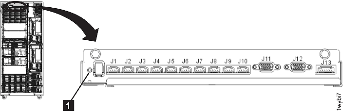
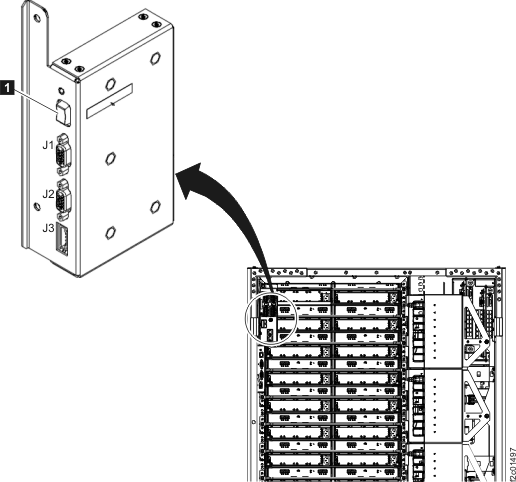
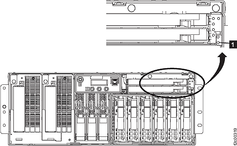
MAP1240 Section-10 (RPC card)
Procedure
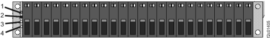
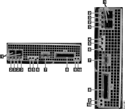
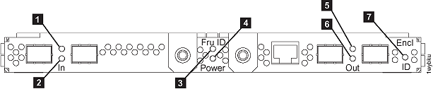
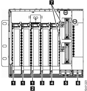
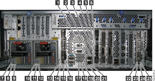
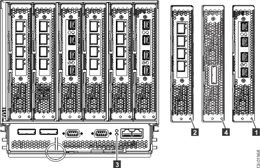
At the rear of the rack, find the RPC card with the flashing identify LED:
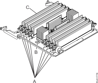
Figure 40. Memory card and memory module LED indicators
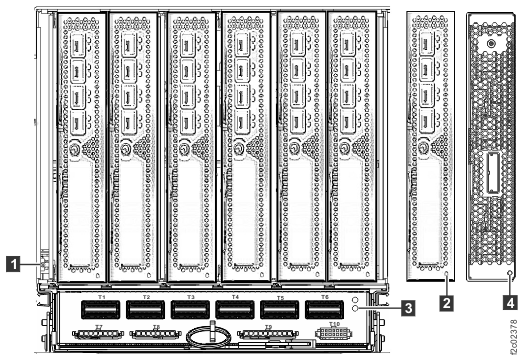
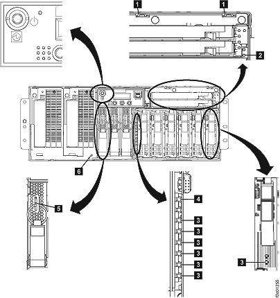
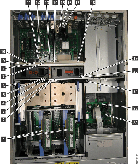
MAP1240 Section-15 (CEC Enclosure
Model 98x)
Procedure
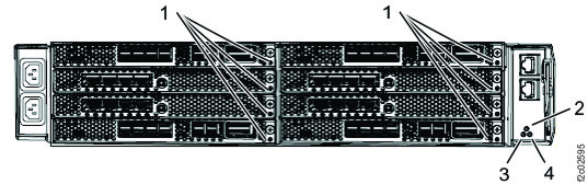
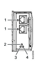
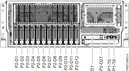
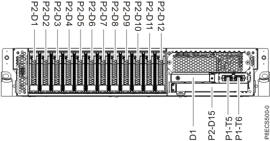
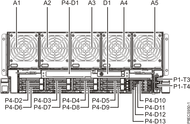
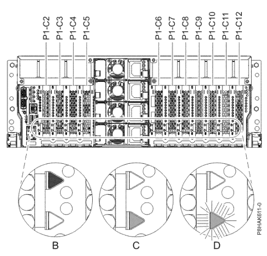
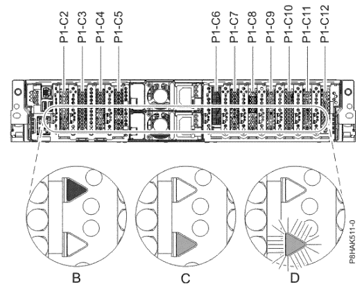
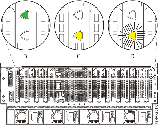
At the front of the rack, find the CEC enclosure with the enclosure identify LED lit solid. The
front identify LED, located on the CEC enclosure control panel assembly, is in Figure 44. The control panel assembly is location D1 in Figure 41, Figure 42, and Figure 43. The
rear identify LED is in Figure 45.
Find the FRU identify LED location using Table 8 and the figures
in this section.
Note: The FRU identify LEDs for several internal CEC components are not visible from outside the CEC
and are not powered when the CEC is in the service position. For these FRUs, location code is used
instead of the identify LED.
Table 8. FRU identify LED locations on the CEC enclosure (Model 98x)
 on each rack in the storage facility.
 is located on the management
enclosure front panel. See Figure 3.
is located on the management
enclosure front panel. See Figure 3.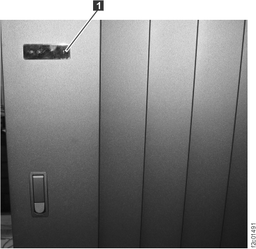
 .
.
 (Figure 13).
 .
.
 lit solid. See Figure 26.
 is shown in Figure 29.
 flashing on one or both FCIC cards.
 in Figure 37.
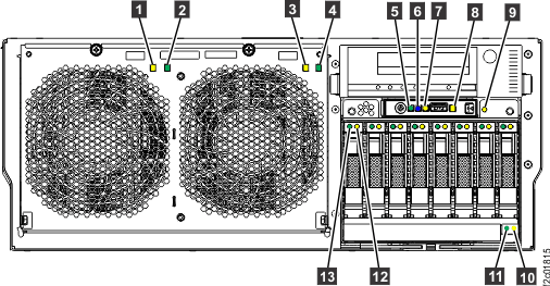


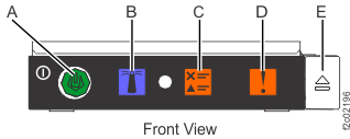
 (press blue button
  to identify)


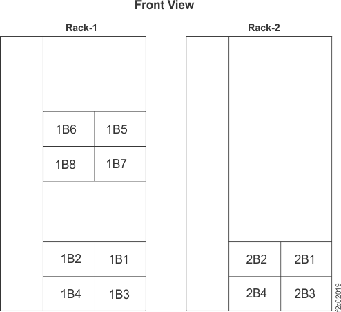 Note: Locations 1B5, 1B6, 1B7 and 1B8 exist in DS8870 all-flash only
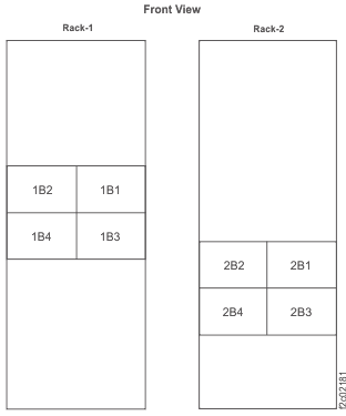 Note: Enclosures 1B1, 1B2, 2B1, and 2B2 are not present in some models.