Exchange the power control network (PCN) cable
Before you begin
 Use approved ESD procedures to prevent damage.
Attention:
- This procedure is not a stand-alone procedure. Customer disruption and damage to the hardware might occur when microcode and power boundaries are not in the proper conditions for this service action.
- If a serviceable event FRU repair directed you to this procedure, the microcode and power boundaries are already set.
- If a serviceable event FRU repair did not direct you to this procedure, see MAP1230 Replace a FRU without using a serviceable event.
Notes:
- All the cables and FRUs to be removed must be uniquely identified so they can be reinstalled correctly.
- If an installed earthquake resistance kit prevents you from accessing this FRU, refer to MAP1600.
Remove the PCN cable
About this task
Note: Both ends of the PCN cable use the same connector.
Procedure
-
Disconnect the PCN cable from the I/O enclosure connectors C9-Tx. See Figure 1 and Table 1.
Table 1. Power control network cabling, Model 983 From RPC card in management enclosure To I/O enclosure (2U) adapter (PCN) C1-J208 1G3-P1-C9-T1 C2-J208 1G3-P1-C9-T2 Figure 1. Power control network (PCN) cables, Model 983 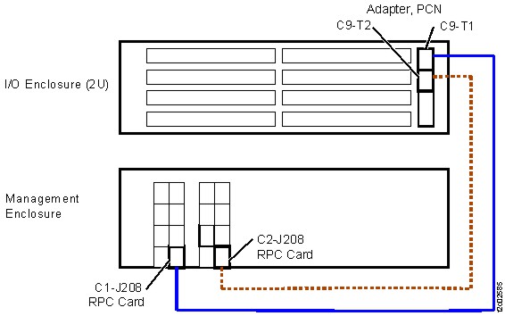
Figure 2. Location codes for the RPC card (Model 983) 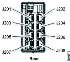
Figure 3. I/O enclosure (2U) locations (rear) 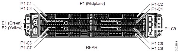
Figure 4. I/O enclosure (2U) adapter (PCN) 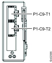
Install the PCN cable
Procedure
- Route the new cable and connect it to the RPC card and I/O enclosure adapter PCN.
- Reinstall the cable retention hardware as needed.
- Exit this service information center parts exchange procedure and return to the procedure that sent you here.