Exchange the SAS cable
Before you begin
CAUTION:
This assembly contains mechanical moving parts. Use care when
you service this assembly. (C025)
 Use approved ESD procedures to prevent damage.
Attention:
- This procedure is not a stand-alone procedure. Customer disruption and damage to the hardware might occur when microcode and power boundaries are not in the proper conditions for this service action.
- If a serviceable event FRU repair directed you to this procedure, the microcode and power boundaries are already set.
- If a serviceable event FRU repair did not direct you to this procedure, see MAP1230 Replace a FRU without using a serviceable event.
Note: All the cables and FRUs to be removed must be uniquely identified so they can be reinstalled
correctly.
Remove the SAS cable
Procedure
-
At the front of the rack, slide the management enclosure out to the service position and remove
the top cover. See Figure 1.
Note: The management enclosure is below the two CEC enclosures.
- Fully loosen the left and right captive thumb screws.
- Slide the management out fully so the sliding rails lock into place.
Figure 1. Management enclosure (front) 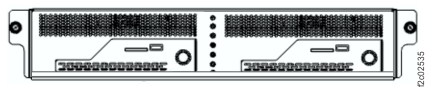
-
At the rear of the SAS flash enclosure, disconnect the SAS cable from the adapter. See Table 1, Figure 2, Figure 3, Figure 4, and Figure 5.
Table 1. SAS cables, I/O enclosure to flash enclosures (Model 983) From I/O enclosure (2U) adapter To SAS flash enclosure adapter I1-1G3-P1-C1-T1 I1-F03-C1-P1-T1 I1-1G3-P1-C1-T2 I1-F03-C2-P1-T1 I1-1G3-P1-C1-T3 I1-F04-C1-P1-T1 I1-1G3-P1-C1-T4 I1-F04-C2-P1-T1 I1-1G4-P1-C8-T1 I1-F03-C1-P1-T2 I1-1G4-P1-C8-T2 I1-F03-C2-P1-T2 I1-1G4-P1-C8-T3 I1-F04-C1-P1-T2 I1-1G4-P1-C8-T4 I1-F04-C2-P1-T2 Figure 2. SAS cable locations (Model 983) 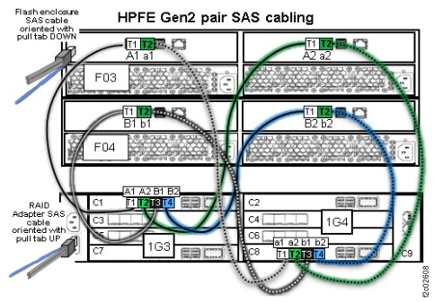
Figure 3. Locations for I/O enclosure (2U) UPS to enclosure power supply cables (Model 983) 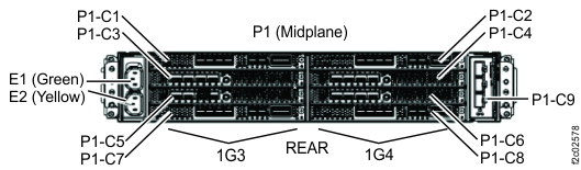
Figure 4. Locations for I/O enclosure (2U) UPS adapter (PCIe and SAS device) (Model 983) 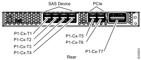
Figure 5. Locations for SAS flash enclosure (rear) (Model 983)