Exchange the Ethernet switch to laptop Ethernet cable
Before you begin
 Use approved ESD procedures to prevent damage.
Attention:
- This procedure is not a stand-alone procedure. Customer disruption and damage to the hardware might occur when microcode and power boundaries are not in the proper conditions for this service action.
- If a serviceable event FRU repair directed you to this procedure, the microcode and power boundaries are already set.
- If a serviceable event FRU repair did not direct you to this procedure, see MAP1230 Replace a FRU without using a serviceable event.
Notes:
- All the cables and FRUs to be removed must be uniquely identified so they can be reinstalled correctly.
- If an installed earthquake resistance kit prevents you from accessing this FRU, refer to MAP1600.
Remove the laptop tray cable assembly
About this task
Note: The I/O enclosure must be fully removed from the rack
for this procedure.
Procedure
- At the rear of the rack, locate the Ethernet switch to
laptop USB Ethernet adapter cable to be replaced.
Figure 1. SW1 (left) black and SW2 (right) gray 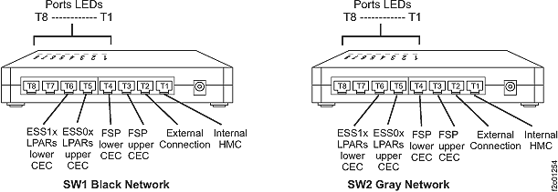
Figure 2. Laptop USB to Ethernet adapter 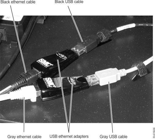
Install the laptop tray cable assembly
Procedure
- Inspect the new cable and find the end that has the location label for the SW-x T1 connector. That goes to the Ethernet switch.
- Route the cable through the cable management arm.
- Connect the cable to the Ethernet switch T1 connector and to the USB Ethernet adapter.
- Connect the USB cable to the USB Ethernet adapter.
- Reinstall the cable retention hardware.
- To verify the black and gray private networks, reference MAP7001 using the network topology tool.
- Exit this service information center parts exchange procedure and return to the procedure that sent you here.