Extending the rack to full height and attaching to the storage facility

About this task

The following lists the sequence to extend the expansion rack (as needed) and attach it to the storage facility.
  • Use the extension hardware to extend the expansion rack to full height (for models with rack extension hardware).
  • Use the merge kit (sometimes called a marriage kit) to fasten the expansion rack to the storage facility.
  • Continue with the installation.
Refer to the following tables for an overview of the parts that are used in various stages of installation.

Procedure

  1. Check now to see if each expansion rack you are installing has EMI seals on the left side of each rack. Record your results.
    Note: The EMI seals are 4 mm wide metallic strips that are attached to the side of the rack near the front, rear, top, and bottom edges.
    • _____ Expansion racks have EMI seals.
    • _____ Expansion racks do not have EMI seals.
  2. Are you installing an expansion rack with rack extension hardware?
  3. You are installing rack extension hardware. Insert wheel chocks (if available) or temporarily lower the stabilizer feet to prevent the rack from moving.
  4. At the top of the rack, remove four screws from each side of the top cover. See Figure 1.
    Notes:
    • The top cover is secured with eight long M10 hex head screws. The extension kit includes a 12 mm deep socket for use with the screws. Store the socket in the document enclosure at the rear of the machine after use.
    • The top cover is raised in stages to three or more different stop points at both the front and rear.

    When the top cover is at the final stop, the extension panels are installed and secured to the frame. After the panels are secure, the top cover is lowered and secured to the extension panels.

    Attention: Apply pressure up and down to ensure that the stop latches engage and hold the top cover at each stop.
    Figure 1. Top cover screw locations
    Top cover screw locations
  5. Raise the top cover to full extension. See Figure 2 and Figure 3.
    1. Release the four safety locking pins, one at each corner of the rack, by pulling out each pin and rotating 1/4 turn.
    2. Lift the rear of the top cover to the first stop. Ensure that the safety latches are engaged.
      Note: Use a light up-and-down force on the top cover to confirm that the latches are engaged.
      Attention: If the latches do not automatically engage or the top cover slips back down, release the safety pins (step 4.a above) only while actively lifting the cover, and engage the safety pins (step 4.g below) at each stop
    3. Lift the front of the top cover to the first stop. Ensure that the safety latches are engaged.
    4. Lift the rear of the top cover to the next stop. Ensure that the safety latches are engaged.
    5. Lift the front of the top cover to the next stop. Ensure that the safety latches are engaged.
    6. Repeat steps d and e until the top cover is fully extended.
    7. Engage the four safety locking pins by rotating each pin about 1/4 turn until it snaps into the frame. Ensure that the pins are fully seated.
      Figure 2. Top cover safety pin
      Top cover safety pin
      Figure 3. Lifting the top cover
      Lifting the top cover
  6. Install and secure the extension panels. The guide pins on each panel point down. See Figure 4 and Figure 5. The screws that are used to secure the panels are described in Table 5.
    Note: The rear panels are larger and have a notch for the top cover struts that is closer to the edge of the panel, as compared to the front panels.
    1. Install the front left extension panel. Secure to frame with two screws at front and rear of panel. Do not tighten the screws at this time.
    2. Install the rear left extension panel. Secure to frame with two screws at front and rear of panel. Do not tighten the screws at this time.
    3. Install the rear right extension panel. Secure to frame with two screws at front and rear of panel. Do not tighten the screws at this time.
    4. Install the front right extension panel. Secure to frame with two screws at front and rear of panel. Do not tighten the screws at this time.
    Figure 4. Extension panel pin locations
    Extension panel pin locations
    Figure 5. Extension panel screw locations
    Extension panel screw locations
  7. Lower the top cover to the top of the extension panels, and secure to the panels. The screws that used to secure the top cover are described in Table 5. They were removed from the top cover at the beginning of this procedure.
    1. Release the four safety locking pins, one at each corner of the rack.
    2. Carefully push down on the rear of the top cover until it rests on top of the rear extension panels.
    3. Carefully push down on the front of the top cover until it rests on top of the front extension panels.
    4. Check that the four safety locking pins have latched. Latch manually, if required.
    5. Insert four screws into each side of top panel, leaving them loose. Screw position is at front and rear of each extension panel.
    6. Tighten the screws that were installed in step 5 to secure the extension panels to the frame. Alternate between the left and right sides of the frame, in the order shown in Figure 7.
    7. Tighten the screws that were installed in step 6 to secure the top panel to the extension panels. Alternate between the left and right sides of the top panel, in the order shown in Figure 7. See Figure 6 and Figure 7.
    Figure 6. Securing the top panel
    Securing the top panel
    Figure 7. Top panel tightening sequence
    Top panel tightening sequence
    Note: the fasteners used for the remainder of this section of the procedure are described in Table 6.
  8. Install the storage enclosure rails.
    1. Install nut clips, if not already present, on the left rear and right rear EIA rails of the extension panels.
      Note: Nut clips are spaced every six holes, following the existing pattern in the storage enclosure section of the rack. The result is nut clips that are installed on the 3rd, 9th, and 15th holes from the top of the extension panel. Refer to Table 1.
    2. For all-flash models 85E, 86E, and 88E install additional nut clips, in top hole and 13th hole from top, on the left rear and right rear EIA rails of the extension panels.
    3. Insert the left and right side rails from the front of the rack, making sure that the rails align with the EIA rail holes front and rear.
    4. At the rear of the rack, secure both the left and right rails with the screws provided.
    Table 1. Nut clip installation in extension panel EIA rails
    Extension panel EIA rail hole (numbered from top) Standard models All-flash models
    1st (top) n/a Install nut clip
    3rd Install nut clip Install nut clip
    9th Install nut clip Install nut clip
    13th n/a Install nut clip
    15th Install nut clip Install nut clip

Important: In the steps that follow, you install storage hardware (storage enclosures, high-performance flash enclosures, or microbays) in the extension section of the rack. Each of these components was packaged separately from the rack you are installing. Take time to identify the locations of these components.

Look for a label that is fastened to the top of the enclosure or microbay. An identical label is found on the side of the package that contains the enclosure or microbay. This label contains the rack identification, rack serial number, and component location.


Example:
  
A-BOX (rack identification - in this case, A-BOX represents Rack-1)
HGD40 (serial number of Rack-1)
F02   (component location - in this case, F02, which is a high-performance flash enclosure)
Table 2. Location designations
Label description Location
A-BOX or RACK-1 Rack-1
B-BOX or RACK-2 Rack-2
C-BOX, C1-BOX, or RACK-3 Rack-3
D-BOX, C2-BOX, or RACK-4 Rack-4
E-BOX, C3-BOX, or RACK-5 Rack-5
Mxx (for example, M02) Microbay location Mxx
Fxx (for example, F02) HPFE location Fxx
Gxx (for example, G02) Storage enclosure location Gxx

  1. At the front of the rack, install the storage enclosures, if additional storage enclosures were provided with the expansion rack.
    Note:
    • This includes both high-performance flash enclosures and FC-AL attached storage enclosures.
    • Storage enclosure components must be removed to meet single-person lifting limits. All components must be labeled before you remove them, and must be reinstalled in their original location.
    • For location of storage enclosures in racks, see Table 3 and Table 4.
    1. Label and remove all drives from each storage enclosure.
    2. Label and remove the FCICs or ESMs from the rear of each storage enclosure.
    3. Label and remove the power supplies from the rear of each storage enclosure.
    4. Install each storage enclosure in its correct location. At the front of the rack, secure to frame at the lower left and lower right of each enclosure with the screws provided.
    5. Reinstall the power supplies, FCICs or ESMs, and drives in their original location in each storage enclosure.
  2. At the front of the rack, install storage enclosure fillers in any empty storage enclosure locations.
  3. At the rear of the rack, install the cable brackets on the rails in extension section storage enclosure locations.
    • G01 and G03 for standard systems. See Table 3.
    • F01 and F03 for all-flash model 88E Rack-2. See Table 4.
    Note: This step does not apply to model 85E Rack-5, or to all-flash racks other than model 88E Rack-2.
    1. Slide the cable bracket  1  onto the bottom of the rail.
    2. Ensure the spring-loaded latches  2  located on either side of the bracket, are secure.
      Figure 8. Cable bracket at the rear of enclosure rails
      Point-to-point cabling diagram for storage enclosure SAS cables (Models 983)
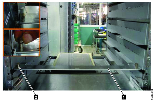
    Table 3. Standard storage enclosure locations, EIA locations 39-46 (machine types 283x, 9581)
    Rack Model EIA location 39-40
    (base rack)
    EIA location 41-42 (extension section) EIA location 43-44 (extension section) EIA location 45-46 (extension section)
    985 Rack-1 G04 G03 G02 G01
    986 Rack-1 G04 G03 G02 G01
    85E Rack-2
    86E Rack-2
    G04 G03 G02 G01
    85E Rack-3, Rack-4, 86E Rack-3, Rack-4, Rack-5 G03 G02 G01 none
    Table 4. Flash enclosure locations, EIA locations 39-46, all-flash models (machine types 533x, 9586)
    Rack Model EIA location 39-40
    (base rack)
    EIA location 41-42 (extension section) EIA location 43-44 (extension section) EIA location 45-46 (extension section)
    985 Rack-1, all flash F06 F05 none none
    986 Rack-1, all flash F08 F07 F06 F05
    988 Rack-1, all-flash F04 F03 F02 F01
    88E Rack-2, all-flash F04 F03 F02 F01
    85E Rack-2, all-flash
    86E Rack-2, all-flash
    88E Rack-3, all-flash
    none none none none
  4. Route and connect the FC-AL cables to the storage enclosure FCICs, if additional storage enclosures were installed.
  5. For model 88E Rack-2, at the rear of the rack, if additional high-performance flash enclosures were installed in the extension section (EIA locations 39 to 46), route and connect the SAS cables to the high-performance flash enclosure ESMs. The cables are grouped by ESM location (C1 or C2). Routing is shown in Figure 9.
    • Cables are routed to the cable bracket from the upper and lower enclosure of each enclosure pair.
    • Cables that are attached to the left ESM (Fxx-C1) of each enclosure are routed to the left side of the bracket, then down to the cable bracket at EIA location 40.
    • Continue routing the cables across the cable bracket at EIA location 40 to the rack-to-rack access hole at the right rear of the rack.
    • Cables that are attached to the right ESM (Fxx-C2) of each enclosure are routed to the right side of the bracket, then down to the rack-to-rack access hole at the right rear of the rack.
    Figure 9. SAS cable routing
    SAS cabling routing
  6. Route and connect the power cables to the storage enclosure or flash enclosure power supplies, if additional storage or flash enclosures were installed.
  7. Install the front door extension.
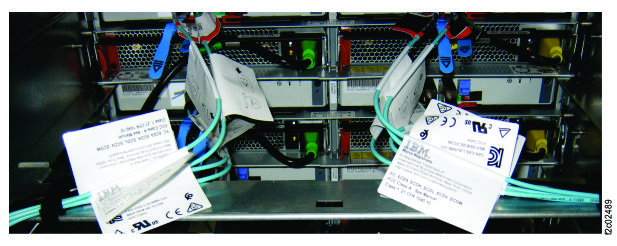
  8. Install the rear door extension.
    Figure 10. Installing the door extension
    Note: Rear door shown, front door is similar
    Installing the door extension
  9. Go to the next section.

    The following tables provide a summary of the hardware that is used to extend a rack to full height (extension kit) and to fasten two racks together (merge kit).

    The part numbers are subject to change.

    Table 5 and Table 6 list the hardware that is used in an extension kit. Table 7 lists the hardware that is used in a rack merge kit for expansion racks without preinstalled EMI seals. Table 8 lists the hardware that is used in a rack merge kit for expansion racks EMI seals.
    Table 5. Extension kit (mechanical bracing)
    Part Part number Purpose Found in
    Top cover screw

    (M10, long hex head)

    00YM643 Secure top cover to extension panel (if used) or to base frame Top cover of rack as shipped
    Extension panel screw

    (M10 x 30)

    98Y6729 or equivalent Secure extension panel to base frame Ship group (extension kit)
    Front right 6U extension panel 98Y7486 EIA rail and mechanical bracing Ship group (extension kit)
    Rear right 6U extension panel

    (left side when viewed from rear)

    98Y7487 EIA rail and mechanical bracing Ship group (extension kit)
    Front left 6U extension panel 98Y7329 EIA rail and mechanical bracing Ship group (extension kit)
    Front left 6U extension panel 02AM766 EIA rail and mechanical bracing, with EMI seals (used on expansion racks with EMI seals) Ship group (extension kit)
    Rear left 6U extension panel

    (right side when viewed from rear)

    98Y7330 EIA rail and mechanical bracing Ship group (extension kit)
    Rear left 6U extension panel

    (right side when viewed from rear)

    02AM767 EIA rail and mechanical bracing, with EMI seals (used on expansion racks with EMI seals) Ship group (extension kit)
    Socket, 12 mm deep (1/4 inch drive) 98Y8397 Loosen and tighten top cover screws Ship group (extension kit)
    Table 6. Extension kit (side covers and rails)
    Part Part number Purpose Found in
    Screw, M4 x 10 15R9571 Secure 6U extensions to front and rear door Ship group (extension kit)
    Screw, M4 x 10 15R9571 Secure 6U side extension cover to rack Ship group (extension kit)
    Extension panel 6U side cover 98Y6945 Cover side of rack with 6U extension Ship group (extension kit)
    Screw, M5 x 16 23R1521 Secure storage enclosure rails to frame Ship group (extension kit)
    Nut clip, M5 74F1823 Secure storage enclosure rails to frame Ship group (extension kit)
    Screw, M5 x 16 23R1521 Secure storage enclosure to rails Ship group (extension kit)
    Table 7. Rack merge kit (expansion racks without preinstalled EMI seals)
    Part Part number Purpose Found in
    Right vertical trim with EMI gasket, 40U front and rear 00YM625 (note 18.a) EMI shield between racks (mounted on right wall of rack) Ship group (merge kit)
    Right vertical trim with EMI gasket, 6U front and rear 00YM628 EMI shield between racks (mounted on right wall of 6U extension) Ship group (merge kit for 6U extension)
    Right horizontal trim with EMI gasket, top and bottom 00YM626 (note 18.b) EMI shield between racks (mounted on right wall of rack) Ship group (merge kit)
    Left vertical trim (no EMI gasket), 40U front and rear 00YM627 (note 18.c) EMI shield between racks (mounted on left wall of rack) Ship group (merge kit)
    Left vertical trim (no EMI gasket), 6U front and rear 00YM629 EMI shield between racks (mounted on left wall of 6U extension) Ship group (merge kit for 6U extension)
    Screw, M4 x 10 15R9571 Secure EMI trim to racks Ship group (merge kit)
    Screw, M10 x 30 98Y6729 Fasten racks together Ship group (merge kit)
    Washer, M10 41U8933 Fasten racks together Ship group (merge kit)
    Notes:
    1. A two-piece trim kit (00YM947 and 00YM948, or equivalent) might be substituted for 00YM625.
    2. A two-piece trim kit (00YM951 and 00YM952, or equivalent) might be substituted for 00YM626.
    3. A two-piece trim kit (00YM949 and 00YM950, or equivalent) might be substituted for 00YM627.
    Table 8. Rack merge kit (expansion racks with EMI seals)
    Part Part number Purpose Found in
    Screw, M10 x 30 98Y6729 Fasten racks together Ship group (merge kit)
    Washer, M10 41U8933 Fasten racks together Ship group (merge kit)
    Note: Expansion racks with EMI seals do not require a separate trim kit for EMI shielding.