Routing and connecting customer cables to the storage facility

Procedure

  1. Ask the customer to supply a diagram or output from the DS8000® Storage Manager to define the connectivity between the DS8000 host card ports and system host card ports.
  2. Label host cables (Fibre Channel) coming from each customer host adapter.
    Note: To allow correct connection and disconnection of external cables, label cables by using the customer's current cable-identification plan and the labels that are provided by your customer.
  3. Route the cables to the rear of the appropriate rack.
  4. Open the cable retention fasteners as required.
  5. This step provides information useful for connecting customer host cables to the I/O enclosure host adapter card ports.
    1. The customer can reference the host adapter port locations by using the information that is displayed in the DS Storage Manager or DS CLI.
    2. For an example of DS Storage Manager I/O port information, see Figure 1.
    3. For an example of DS CLI I/O port information, see Figure 2.
    4. For information on host adapter card port location codes that are used in serviceable event FRU lists, see Figure 3 and Figure 4.
    5. For information on I/O enclosure host adapter (HA) port locations and IOPORT numbers, see Table 1.
    Figure 1. DS Storage Manager HA card port ID and location code
    DS Storage Manager HA card port ID and location code
    Figure 2. DS CLI Host adapter card port ID
    
    dscli> lsioport -dev IBM.2107-75RA271
    Date/Time: July 13, 2010 2:40:33 PM PDT IBM DSCLI Version: 5.4.2.460 DS: IBM.2107-75RA271
    ID    WWPN             State  Type             topo     portgrp
    ===============================================================
    I0200 50050763091006FE Online Fibre Channel-SW SCSI-FCP 0
    I0201 50050763091046FE Online Fibre Channel-SW SCSI-FCP 0
    Figure 3. I/O enclosure (2U) locations code (rear) (model 983) 1G3, 1G4
    I/O enclosure (2U) locations code (rear) (model 983) with logical IG3, 1G4
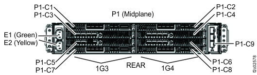
    Figure 4. I/O enclosure (2U) adapter (Fibre Channel host)
    I/O enclosure (2U) adapter (Fibre Channel host)
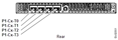
    Figure 5. Location codes, I/O enclosure (2U) adapter(PCIe and SAS device)
    I/O enclosure (2U) adapter (PCIe and SAS device)
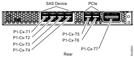
    Note: SAS device version shown. Port location is similar on adapter without SAS device ports.
    Table 1. Rear view of I/O enclosure host adapter port locations and IOPORT numbers
    I/O enclosure 1G3   I/O enclosure 1G4
    PCIe adapter slot C1                   PCIe adapter slot C2
    Host adapter slot C3 C3-T0

    I0230

    C3-T1

    I0231

    C3-T2

    I0232

    C3-T3

    I0233

      C4-T0

    I0330

    C4-T1

    I0331

    C4-T2

    I0332

    C4-T3

    I0333

    Host adapter slot C4
    Host adapter slot C5 C5-T0

    I0240

    C5-T1

    I0241

    C5-T2

    I0242

    C5-T3

    I0243

      C6-T0

    I0340

    C6-T1

    I0341

    C6-T2

    I0342

    C6-T3

    I0343

    Host adapter slot C6
    PCIe adapter slot C7                   PCIe adapter slot C8
  6. Route the Fibre Channel cables to the destination I/O enclosure as appropriate for the rack used. Route the cables to the host adapters and plug them in.
    Important: The optical cable plugs (LC connectors) and ports (SFPs) must be cleaned before connecting them. Use cleaning tool 54Y4392 or IBM-approved alternative. After cleaning SFPs with the tool, use air bulb 45D2645 or IBM-approved alternative. For detailed procedures, refer to current DS8000 Info Alerts or contact your next level of support.
  7. Secure the host cables as appropriate for the rack used.
  8. Go to Finish installation and cleanup.