Finish installation and cleanup

Procedure

  1. You must use the next step to ensure that the storage facility power control mode is set to Manual unless the customer selected a different setting on the customer worksheet.
  2. Set the storage facility rack power control mode that the customer chose on the configuration worksheet. For more information, see MAP2460 Configuring and overview of the DS8000 Power Control Mode.
    1. From the navigation area, click Storage Facility Management.
    2. From the right work area, select the radio button for the existing storage facility. The bottom Task area displays a list of tasks you can select.
    3. Click Service Utilities.
    4. Click Storage Facility Power Control
    5. Make the desired customer selections from the worksheets.
  3. Compare the control switch settings that are defined on the Customization Worksheet with the default settings in Table 1.
    Table 1. Control switch default settings
    Control Switch Setting Default Value
    AS400 LUN Serial Suffix number 0
    CUIR support 0 (false)

    Do the customization worksheet control switch settings match the default settings in Table 1?

    • Yes, continue with the next step.
    • No, from the HMC GUI perform the following steps to alter the Control Switch Settings for each storage facility image that must be updated.
      1. From the navigation area, click Storage Facility Management > storage facility > SF image.
      2. From the bottom Task area, click Service Utilities > Enable/Disable Control Switches. The Control Switches - SF Image window opens.
      3. Update the values from the Customization Worksheets. Click Set.
      4. Continue to the next step.
  4. Place the following items in the document enclosure or customer-provided storage for future use or reference:
    • Copies of the configuration worksheets
    • Spare ship group components
    • CDs/DVDs
    • Spare labels
    • Cable planning worksheets
    • Host card wrap tools
    • DVD drive
  5. Use the Network Topology Tool to verify connectivity with all nodes (Ethernet ports) on the DS8000 private network and then save the topology. The following lists examples of nodes.
    • Local HMC ports.
    • HMC ports on second HMC (if installed).
    • CEC enclosure service processor Ethernet ports (HMC ports).
    • LPAR (partition) ports on the CEC enclosure Ethernet adapter.

    Start the Network Topology tool as follows:

    1. From the navigation area, click HMC Management.
    2. In the right work area, go to the Operations section and click View Network Topology.
    3. Wait several minutes for the tool to gather and present the results.
    4. A window opens and displays the current network topology (port connections) listed on top, and the saved topology from the last time the tool was run and the Save button was selected. Normally the saved topology should be from results when all nodes on both private networks were fully present and operational.
      Note: The option to save the topology is used after all nodes on both private networks are determined to be present and operational.
    5. Determine if all expected nodes are present. Refer to Figure 1, Figure 2, and the saved topology nodes list.
    6. Are any nodes missing or failing?

    Figure 1 shows an example of a Network Topology window with a single management console. Figure 2 shows an example of a full topology tree for a single HMC and single storage facility.

    Figure 1. Network Topology window (Current Topology area is shown)
    Screen capture of a current network topology
    Figure 2. Full topology example with one management console
    Screen capture of an example of a full topology with one management console
    Figure 3. Diagram of network topology (example shows 8-port switches)
    Diagram of network topology (example shows 8-port switches)
    Notes:
    • The tool provides a hierarchical view of the network from the management console which you logged in to.
    • The Current Topology view shows the status of detected nodes on each of the two DS8000 private networks at the time the tool was started or when Refresh was selected.
    • The service processor cards are accessed through one of the two networks, so they will not appear on both. This is normal.
    • The Storage Facility system status information is displayed along with the associated service processor card, so it will not appear on both networks. This is normal.
  6. If there is a second HMC in this storage complex, use the Network Topology tool (step 5) on the second HMC, then go to step 7.
  7. In the View Network Topology panel, click Close to close the panel.
  8. Store the customer provided configuration worksheets in the Rack 1 document enclosure (left rear of rack).
  9. Use the View Storage Facility Status utility to ensure there are no unreported or unexpected problems or conditions.
    1. From the navigation area, click Storage Facility Management > storage facility.
    2. From the bottom Task area, click Service Utilities > View Storage Facility State.
    3. A window opens listing passed/failed status for 25 or more system checks. You can display the details for each system check.
      Note: Further explanations and options are detailed in MAP1100 View storage facility state (end of call).
  10. At the front of the rack, observe the CEC enclosure system attention blue LED indicator  C  on the operator panel above the disk drives.
    Is the indicator lit?
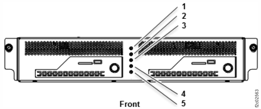
    • Yes. Because the prior step determined that there are no unexpected or reported problems, this is a false system attention indication. You must switch off the system attention indicator. Go to MAP4050 Switching off the CEC enclosure system attention indicator (lit solid), then return here and continue with the next step.
      Note: When the CEC enclosure attention indicator is lit solid, the system attention LED  5  on the management enclosure operator panel will also be lit solid. See Figure 5
    • No, go to the next step.
    Figure 4. Control panel LEDs
    Control panel LEDs
    Figure 5. Management enclosure front panel
    Management enclosure front panel
  11. Reference the pack/unpack instructions for return/discard information. Discard the shipping material locally.
  12. The storage facility is now regarded as Installation complete.
    1. Record the stop date and time for the HMC initial configuration through end of installation and clean up phase in Table 2 and Table 3 in section Recording information for the installation report.
    2. Update the account records to show that the installation is complete.
    3. Record any additional time to install features, ECs, and MESs to the correct service code. Do not charge the additional time to the DS8000 installation.
    4. Go to the next step.
  13. Determine whether the management console software or storage facility LIC level must be updated by completing the steps that follow. Compare the installed versions with the versions determined in the task Checking for required microcode .
    1. To display the level of management console software, from the navigation area click Updates. Select the HMC, then from the bottom Task area click Display Installed HMC Code Levels.
    2. To display the storage facility code level, from the navigation area, click Updates. Select the storage facility, then from the bottom Task area click Display Storage Facility Code Levels.

    Does the management console software or storage facility LIC need to be updated?

    • Yes, go to step 15.
    • No, go to the next step.
  14. The onsite service actions are now complete.
    1. Inform the customer that the machine will be available for configuration when the drive certification completes.
    2. Upon receipt of the call-home, the IBM® support center calls the contact name and telephone number entered earlier and inform them that the DS8000 is now available.
      Note: For all-flash systems there is no drive certify process to monitor. Use Table 4, in section Recording information for the installation report to record 00.0 for the start time, stop time, and number of hours for the Monitor drive certify phase.
    3. Go to step 16
  15. Acquire and install the LIC bundle.
    1. Refer to the Microcode installation instructions to acquire the LIC bundle.
      Note: For all-flash systems there is no drive certify process to monitor. Use Table 4, in section Recording information for the installation report to record 00.0 for the start time, stop time, and number of hours for the Monitor drive certify phase.
    2. Use the supplied LIC Installation Instructions to update the storage facility LIC.
      Note: Use Table 4, in section Recording information for the installation report to record 00.0 for the start time, stop time, and number of hours for the Monitor drive certify phase.
    3. When the LIC is complete, inform the customer that the storage facility is now available for configuration.
      Note: Use Table 4 in section Recording information for the installation report to record the stop date and time for the SF Code Upgrade (SC33) phase.
    4. Go to step 16.
  16. If the customer has purchased LIC features, the customer is responsible for retrieving the keys and activating the licenses by using the procedures in the IBM DS8000 Introduction and Planning Guide for your model.
    Note: If the customer cannot access the keys on the DSFA website the customer is instructed to open a service call. The service representative can have their next level of support manually generate and provide the keys to the customer.
  17. The customer is responsible for creating and managing all logical configuration of the racks being installed. If the customer has problems creating the logical configuration, they might come to you for help. You can check for any open serviceable events that are related to the I/O enclosures or storage enclosures to be repaired. If there are none, have the customer contact IBM support and ask for software help with the logical configuration and the GUI interface.
  18. Complete the storage facility Install report.
    1. In the DS8000 storage management GUI, click Service > Install Hardware > Generate Install Report.
  19. Logout of the HMC. Stow the keyboard and display as needed for your configuration.
  20. Reinstall any front or rear covers that were removed.
  21. Close the rear door, if required.
  22. Close the front door, if required. The onsite installation activity is complete.