MAP1100 View storage facility state (end of call)
An all-in-one service utility function that displays the storage facility state, similar to the 2105 End of Call.
MAP1100 Section-1
Procedure
-
View the storage facility state (end of
call).
Figure 1. Window: View Storage Facility State 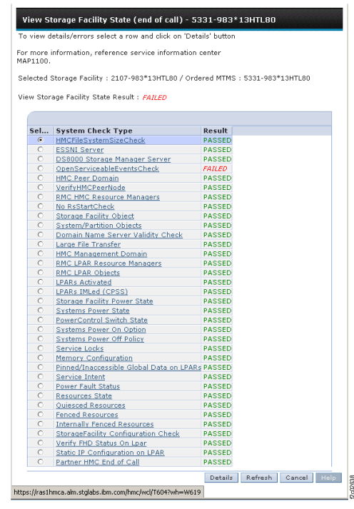
MAP1100 Section-2, HMCFilesystemSizeCheck
Procedure
- Figure 2 is
an example of the detail window for the HMCFileSystemSizeCheck (in
this example, an error condition is not shown).
Figure 2. Window: HMCfilesystemSizeCheck details 
MAP1100 Section-3, ESSNI Server
Procedure
- Figure 3 is
an example of the Details window for the ESSNI
Server.
Figure 3. Window: ESSNI server details 
MAP1100 Section-4, DS8000 Storage Manager Server
Procedure
-
Figure 4 is an example of the
detail window for the DS8000 Storage
Manager server (in this
example, an error condition is not shown).
Figure 4. Window: DS8000 Storage Manager server details 
MAP1100 Section-5, OpenServiceableEvents Check
Procedure
-
Figure 5 is an example of the
detail window for the open serviceable event
details.
Figure 5. Window: Open serviceable events details 
MAP1100 Section-6, HMC Peer Domain
Procedure
- Figure 6 is an example of the
detail window for the HMC peer domain (in this example, an error condition
might not be shown).
Figure 6. Window: HMC peer domain details 
MAP1100 Section-7, Verify HMC Peer Node
Procedure
- Figure 7 is an example of the
detail window for the HMC peer node (in this example, an error condition
is not shown).
Figure 7. Window: HMC peer node details 
MAP1100 Section-8, RMC HMC Resource Managers
Procedure
- Figure 8 is an example of the
detail window for the RMC HMC resource managers (in this example,
an error condition is not shown).
Figure 8. Window: RMC HMC resource managers details 
MAP1100 Section-9, Storage Facility Object
Procedure
-
Figure 9 is an example of the
detail window for the storage facility object (in this
example, an error condition is not shown).
Figure 9. Window: Storage facility object details 
MAP1100 Section-10, System/Partition Object
Procedure
- Figure 10 is an example of the
detail window for the System/partition object (in this example, an
error condition is not shown).
Figure 10. Window: System/partition object details 
MAP1100 Section-11, Large File Transfer
Procedure
- Figure 11 is
an example of the detail window for large file transfers (in this
example, an error condition is not shown).
Figure 11. Window: Large file transfer details 
MAP1100 Section-12, HMC Management Domain
About this task
Note: If
the Large File Transfer (the 10th System Check Type status from the top) is FAILED, this
System Check Type cannot be displayed.
Procedure
- Figure 12 is an example of the
detail window for the HMC management domain (in this example, an error
condition is not shown).
Figure 12. Window: HMC management domain details 
MAP1100 Section-13, RMC LPAR Resource Managers
About this task
Note: If
the Large File Transfer (the 10th System Check Type status from the top) is FAILED, this
System Check Type cannot be displayed.
Procedure
- Figure 13 is an example of the
detail window for the RMC LPAR resource managers (in this example,
an error condition is not shown).
Figure 13. Window: RMC LPAR resource managers details 
MAP1100 Section-14, RMC LPAR Objects
About this task
Note: If
the Large File Transfer (the 10th System Check Type status from the top) is FAILED, this
System Check Type cannot be displayed.
Procedure
- Figure 14 is an example of the
detail window for the RMC LPAR objects (in this example, an error
condition is not shown).
Figure 14. Window: RMC LPAR object details 
MAP1100 Section-15, LPARs Activated
About this task
Note: If
the Large File Transfer (the 10th System Check Type status from the top) is FAILED, this
System Check Type cannot be displayed.
Procedure
- Figure 15 is an example of the
detail window for the LPARs that are activated (in this example, an
error condition is not shown).
Figure 15. Window: LPARs activated details 
MAP1100 Section-16, LPARs IMLed (CPSS)
About this task
Note: If
the Large File Transfer (the 10th System Check Type status from the top) is FAILED, this
System Check Type cannot be displayed.
Procedure
- Figure 16 is
an example of the detail window for the LPARs IMLed (CPSS) (in this
example, an error condition is not shown).
Figure 16. Window: LPARs IMLed (CPSS) details 
MAP1100 Section-17, Storage Facility Power State
About this task
Note: If
the Large File Transfer (the 10th System Check Type status from the top) is FAILED, this
System Check Type cannot be displayed.
Procedure
-
Figure 17 is an example of the
detail window for the storage facility power state (in
this example, an error condition is not shown).
Figure 17. Window: Storage facility power state details 
MAP1100 Section-18, Systems Power State
About this task
Note: If
the Large File Transfer (the 10th System Check Type status from the top) is FAILED, this
System Check Type cannot be displayed.
Procedure
- Figure 18 is an example of the
detail window for the systems power state (in this example, an error
condition is not shown).
Figure 18. Window: Systems power state details 
MAP1100 Section-19, Systems Power-on Option
About this task
Note: If
the Large File Transfer (the 10th System Check Type status from the top) is FAILED, this
System Check Type cannot be displayed.
Procedure
- Figure 19 is an example of the
detail window for the systems power on option (in this example, an
error condition is not shown).
Figure 19. Window: Systems power on options details 
MAP1100 Section-20, Systems Power Off Policy
About this task
Note: If
the Large File Transfer (the 10th System Check Type status from the top) is FAILED, this
System Check Type cannot be displayed.
Procedure
- Figure 20 is
an example of the detail window for the system power off policy (in
this example, an error condition is not shown).
Figure 20. Window: Systems power off policy details 
MAP1100 Section-21, Service Locks
About this task
Note: If
the Large File Transfer (the 10th System Check Type status from the top) is FAILED, this
System Check Type cannot be displayed.
Procedure
- Figure 21 is
an example of the detail window for the systems power on option (in
this example, an error condition is not shown).
Figure 21. Window: Service locks details 
MAP1100 Section-22, DA Load State
About this task
Note: If
the Large File Transfer (the 10th System Check Type status from the top) is FAILED, this
System Check Type cannot be displayed.
Procedure
- Figure 22 is an example of the
detail window for the DA (device adapter card) load state (in this example, an error condition
is shown).
Figure 22. Window: Device adapter load state details 
MAP1100 Section-23, Pinned Data on LPARs
About this task
Note: If
the Large File Transfer (the 10th System Check Type status from the top) is FAILED, this
System Check Type cannot be displayed.
Procedure
- Figure 23 is
an example of the detail window for the pinned data on LPARs (in this
example, an error condition is not shown).
Figure 23. Window: LPARs pinned data details 
MAP1100 Section-24, Service Intent
About this task
Note: If
the Large File Transfer (the 10th System Check Type status from the top) is FAILED, this
System Check Type cannot be displayed.
Procedure
- Figure 24 is
an example of the detail window for the "service intent" when a DA
card FRU is being replaced. This figure shows the displayed status
for a model 9A2,
dual SFI. Notice that status for both SFIs is displayed.
Figure 24. Window: Check service intent details 
MAP1100 Section-25, Display Details for a Resource State
About this task
Note: If
the Large File Transfer (the 10th System Check Type status from the top) is FAILED, this
System Check Type cannot be displayed.
Procedure
- Figure 25 is
an example of the detail window for the resources state (in this example,
an error condition is not shown).
Figure 25. Window: Details of a resource state 
MAP1100 Section-26, Quiesced Resources
About this task
Note: If
the Large File Transfer (the 10th System Check Type status from the top) is FAILED, this
System Check Type cannot be displayed.
Procedure
- Figure 26 is an example of the
detail window for the quiesce resource (in this example, an error
condition is not shown).
Figure 26. Window: Quiesce resource details 
MAP1100 Section-27, Fenced Resources
Procedure
- Figure 27 is an example of the
detail window for the fenced resources (in this example, an error
condition is not shown).
Figure 27. Window: Fenced resources details 
MAP1100 Section-28, Displaying Resource States
Procedure
Perform the following steps to determine the resource state:
- Scroll down to see the states of the various resources.
Figure 28. Window: View Resource States 
MAP1100 Section-29, Storage Facility Power State
Procedure
MAP1100 Section-30, CEC enclosure
About this task
Procedure
Perform the following steps to determine the state of the storage facility systems:
- From the navigation area, click .
- In the right content area, find the storage facility state. For example, Server-9117-MMA-SN13AABF0 Operating.
MAP1100 Section-31, Storage Facility Partitions
Procedure
Perform the following steps to determine the state of the storage facility partitions:
- From the navigation area, click .
- In the right content area, find the storage facility state. For example, Server-9117-MMA-SN13AABF0 Operating.
- Find the storage facility partition state. For example, SF1300150ESS11 Running.
MAP1100 Section-32, Storage Facility Image LPARs
Procedure
MAP1100 Section-33, Storage Facility Images
Procedure
MAP1100 Section-34, Not Used
About this task
MAP1100 Section-35, Host Adapters and Ports
Procedure
MAP1100 Section-36, Device Adapter
Procedure
MAP1100 Section-37, Display Rack Power System Resources
Procedure
Perform the following steps to determine the state of the RPC cards:
Note: The normal state is Available.
-
Select a rack and then click Show FRUs.
The Show Rack FRUs window opens. See Figure 29.
Figure 29. Window: Show Rack FRUs 
MAP1100 Section-38, DDMs State
Procedure
MAP1100 Section-39, FCIC Card State
Procedure
MAP1100 Section-40, Memory Configuration
Procedure
- Figure 30 is
an example of the detail window for the memory configuration check
(in this example, an error condition is not shown).
Figure 30. Window: Memory configuration details 
MAP1100 Section-41, Tower I/O Settings
About this task
MAP1100 Section-42, Power Control Switch State
Procedure
- Figure 31 is an example of the
details window for the Power Control Switch check.
Figure 31. Window: PowerControl switch details 
- Action:
- At the rear of Rack-1, observe
the position of the local remote switch on the local remote switch
card. It should be in the REMOTE position. It should be in the LOCAL
position only if directed by next level of support or an isolation
MAP for the special case where the management console could not control
the storage facility power.
- If the state is displayed as LOCAL, observe the local remote switch
position.
- If the switch is in LOCAL, complete the service action that had you set it to local. If there is no service action in progress, reset the switch back to REMOTE.
- If the switch is in REMOTE, there is a problem with the physical setting of the switch not agreeing with the setting reported by the code. Contact your next level of support.
- If the state is displayed as REMOTE, this state is correct if the switch is in the REMOTE position. If the switch is in the LOCAL position, contact your next level of support.
Figure 32. Model 961 local remote switch card (zSeries local remote switch card similar) 
Figure 33. Model 98x local remote switch card 
- If the state is displayed as LOCAL, observe the local remote switch
position.
- At the rear of Rack-1, observe
the position of the local remote switch on the local remote switch
card. It should be in the REMOTE position. It should be in the LOCAL
position only if directed by next level of support or an isolation
MAP for the special case where the management console could not control
the storage facility power.
MAP1100 Section-43, Power Fault Status
About this task
- Figure 34 is an example of the details window for the Power Fault Status check.
- Description: Verifies whether there are any power fault
in CEC and I/O enclosures:
- Details panel indicates which CEC/tower components have power faults.
- When no faults are detected, the details panel lists each CEC/tower location code and indicate that no faults are found.
- Action: On a failed check, for better problem isolation, run the
cdaPreVerify utility. Refer to MAP1214 Run CdaPreVerify
The cdaPreVerify utility runs through a fault status check and generates the serviceable events with following SRCs:
- SRC for failed power supply: BE9C1B5B
- SRC for logic error during power supply verification: BE9C1B5E
Figure 34. Window: Power fault status details 
MAP1100 Section-44, SPCN Loop Status
About this task
- Figure 35 shows an example of the details window for the SPCN loop status check.
- Description: Verifies whether the SPCN loop is complete
on both CECs:
- The Details panel indicates whether the SPCN loop is complete on each CEC.
- When an OPEN loop is detected, it indicates the CEC that has open loop.
- Action: On a failed check, for better problem isolation, run the
cdaPreVerify utility. Refer to MAP1214 Run CdaPreVerify. The cdaPreVerify utility runs through an SPCN loop check and might result in a serviceable event with following SRC:
- SRC for open SPCN loop: BED10470
MAP1100 Section-45, norsStart check
Procedure
- Figure 36 is an example
of the details window for the norsStart check.
Figure 36. Window:norsStart check details 
MAP1100 Section-46 RIO Loop Status
About this task
- Figure 37 shows an example of the details window for the RIO Loop Status check (in this example, a good condition is shown).
- Description: Verifies from each CEC whether the RIO loop
is complete:
- The Details window indicates whether there are open RIO loops.
- When an open loop is detected, the following message is displayed:
Detected problem in RIO Loop. Please run CdaPreVerify to isolate the problem in RIO loop.
- Action: On failed check, run CdaPreVerify to isolate the problem in the RIO loop. CdaPreVerify might open more serviceable events to isolate the problem. Refer to MAP1214 Run CdaPreVerify.
MAP1100 Section-48 Internally Fenced Resources
Procedure
- #map1100section-48__d891e32 displays
an example of the detail window for internally fenced resources (in
this example, an error condition is not shown).
Figure 38. Window: Internally fenced resources details