CEC enclosure location codes (Models 982, 988)
You can identify the CEC enclosure in which a field replaceable unit (FRU) is plugged by its
location code. The first character of the location code is always
U followed by a
four-character feature code or enclosure type, as shown in the following example:- U78C7.001.10ABCDE-P2-C14
78C7. The next three characters of the
location code indicate the model of the enclosure (001 in the example). The next
string of characters provides the enclosure serial number (10ABCDE in the example). CEC enclosures for Models 982, 988 are normally feature code U78C7.001.
The CEC enclosure type (feature code) label is on the top of the CEC enclosure, behind the
front cover, above the drive enclosure.
| Feature code (Utttt) | System | For storage model |
|---|---|---|
| U78C7.001 | 8408-E8E | 982, 988 |
| U78C9.001 | 8286-42A | 981, 985, 986 |
| U78CB.001 | 8284-22A | 980, 984 |
Table 2 summarizes the CEC enclosure assembly
with references to figures that display location codes.
For part numbers, see CEC enclosure part numbers, Models 982, 988.
CEC enclosure front overview
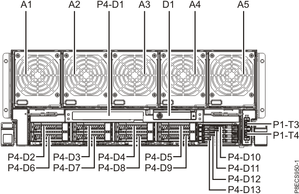
| Location code | Part name | Connector |
|---|---|---|
| Un-A1 | CEC enclosure fan 1 | |
| Un-A2 | CEC enclosure fan 2 | |
| Un-A3 | CEC enclosure fan 3 | |
| Un-A4 | CEC enclosure fan 4 | |
| Un-A5 | CEC enclosure fan 5 | |
| Un-A6 to A9 | CEC enclosure fan 6 - 9 See Figure 4 and Table 6 |
|
| Un-D1 | CEC enclosure control panel assembly | |
| Un-P1 | CEC enclosure I/O backplane See Figure 2, Table 4, Figure 3, and Table 5 |
|
| Un-P1-T3 Un-P1-T4 |
Not used | USB 3.0 |
| Un-P2 | CEC enclosure system backplane See Figure 2 and Table 4 |
|
| Un-P3 | CEC enclosure RAID card See Figure 4 and Table 6 |
|
| Un-P4 | CEC enclosure disk drive backplane See Figure 4 and Table 6 |
|
| Un-P4-D1 | Not used | |
| Un-P4-D2 to D9 | CEC enclosure disk drive | |
| Un-P4-D10 to D13 | Not used |
CEC enclosure top overview
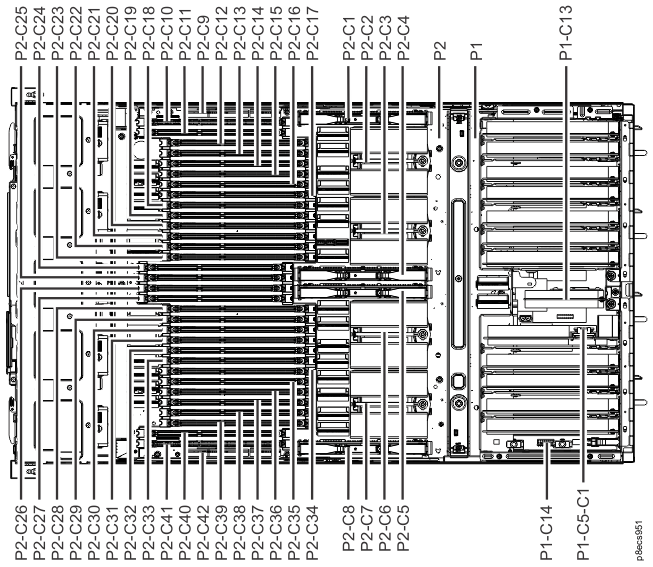
| Location code | Part name | Connector |
|---|---|---|
| Un-P1 | CEC enclosure I/O backplane | |
| Un-P1-C5 | CEC enclosure service processor card | |
| Un-P1-C5-C1 | CEC enclosure time-of-day battery card | |
| Un-P1-C13 | CEC enclosure I/O voltage regulator module (VRM) | |
| Un-P1-C14 | CEC enclosure vital product data (VPD) card | |
| Un-P2 | CEC enclosure system backplane | |
| Un-P2-C1 | CEC enclosure processor voltage regulator module (VRM) 1 | |
| Un-P2-C2 | CEC enclosure processor module 1 | |
| Un-P2-C3 | CEC enclosure processor module 2 | |
| Un-P2-C4 | CEC enclosure processor VRM 2 | |
| Un-P2-C5 | CEC enclosure processor VRM 3 | |
| Un-P2-C6 | CEC enclosure processor module 3 | |
| Un-P2-C7 | CEC enclosure processor module 4 | |
| Un-P2-C8 | CEC enclosure processor VRM 4 | |
| Un-P2-C9 | CEC enclosure memory regulator module (VRM) | |
| Un-P2-C10 to C41 | CEC enclosure memory module | |
| Un-P2-C42 | CEC enclosure memory VRM | |
| Un-P5 | CEC enclosure power midplane (not shown, located under P1) | |
| Un-Y1 | CEC enclosure firmware |
CEC enclosure rear overview
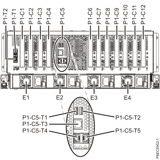
| Location code | Part name | Connector |
|---|---|---|
| Un-E1 | CEC enclosure power supply 1 | |
| Un-E2 | CEC enclosure power supply 2 | |
| Un-E3 | CEC enclosure power supply 3 | |
| Un-E4 | CEC enclosure power supply 4 | |
| Un-P1 | CEC enclosure I/O backplane | |
| Un-P1-C1 | Not used | |
| Un-P1-C2 | CEC enclosure PCIe two-port card | |
| Un-P1-C2-T1 | CXP (PCIe) | |
| Un-P1-C2-T2 | CXP (PCIe) | |
| Un-P1-C3 | CEC enclosure PCIe two-port card | |
| Un-P1-C3-T1 | CXP (PCIe) | |
| Un-P1-C3-T2 | CXP (PCIe) | |
| Un-P1-C4 | Not used | |
| Un-P1-C5 | CEC enclosure service processor card | |
| Un-P1-C5-T1 | Not used | USB 2.0 |
| Un-P1-C5-T2 | Not used | USB 2.0 |
| Un-P1-C5-T3 | Not used | Serial |
| Un-P1-C5-T4 | HMC port 1 (used for private network) | Ethernet (service processor) |
| Un-P1-C5-T5 | HMC port 2 (used for private network) | Ethernet (service processor) |
| Un-P1-C6 | CEC enclosure I2C interface card assembly | |
| Un-P1-C6-T1 | I2C (to RPC) | |
| Un-P1-C6-T2 | I2C (to RPC) | |
| Un-P1-C7 | CEC enclosure RS-485 serial-interface card | |
| Un-P1-C7-T1 | RS-485 serial (to RPC) | |
| Un-P1-C7-T2 | RS-485 serial (to RPC) | |
| Un-P1-C8 | CEC enclosure PCIe two-port card | |
| Un-P1-C8-T1 | CXP (PCIe) | |
| Un-P1-C8-T2 | CXP (PCIe) | |
| Un-P1-C9 | Not used | |
| Un-P1-C10 | CEC enclosure PCIe two-port card | |
| Un-P1-C10-T1 | CXP (PCIe) | |
| Un-P1-C10-T2 | CXP (PCIe) | |
| Un-P1-C11 | CEC enclosure Ethernet four-port card | |
| Un-P1-C11-T1 | Ethernet (LPAR) | |
| Un-P1-C11-T2 | Ethernet (LPAR) | |
| Un-P1-C11-T3 | Ethernet customer network (optional feature, if used) | |
| Un-P1-C11-T4 | Ethernet customer network (optional feature, if used) | |
| Un-P1-C12 | CEC enclosure Ethernet adapter (10 Gb and 1 Gb) | |
| Un-P1-C12-T1 | Ethernet customer network, 10 Gb optical (optional feature, if used) | |
| Un-P1-C12-D2-T11 | ||
| Un-P1-C12-T2 | Ethernet customer network, 10 Gb optical (optional feature, if used) | |
| Un-P1-C12-D2-T21 | ||
| Un-P1-C12-T3 | Ethernet customer network 1 Gb RJ45 (optional feature, if used) | |
| Un-P1-C12-D2-T31 | ||
| Un-P1-C12-T4 | Ethernet customer network 1 Gb RJ45 (optional feature, if used) | |
| Un-P1-C12-D2-T41 | ||
| Un-P1-T1 | Not used | USB 3.0 |
| Un-P1-T2 | Not used | USB 3.0 |
| Un-P5 | CEC enclosure power midplane (not shown, located under P1) | |
|
Notes:
1. Some messages and displays might show this location as Un-P1-C12-D2-Tx instead of Un-P1-C12-Tx. |
||
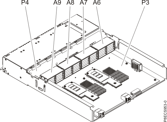
| Location code | Part name | Connector |
|---|---|---|
| Un-A6 | CEC enclosure fan 6 | |
| Un-A7 | CEC enclosure fan 7 | |
| Un-A8 | CEC enclosure fan 8 | |
| Un-A9 | CEC enclosure fan 9 | |
| Un-P3 | CEC enclosure RAID card | |
| Un-P4 | CEC enclosure disk drive backplane |