MAP2801 Replacing the management enclosure 12V power distribution cable

About this task

Replacing the management enclosure 12V power distribution cable requires this non-standard FRU replace procedure.

During this procedure:
  • Both management consoles in the management enclosure are shut down.
  • The storage facility remains in use for customer operation.
  • The customers cannot manage their storage by using these management consoles.
  • The cable FRU is replaced.

MAP2801 Section-1

Before you begin

Before you start this procedure, ensure that the customer understands that there is no access to either management console during this FRU replacement. The estimated time for the procedure is 45 minutes.

Remove the cable FRU

Procedure

  1. Record notes, print this procedure, or take a picture of it. This view of MAP2801 is not available to reference after the next step.
  2. Shut down both management consoles (MC1, MC2) in this management enclosure. Refer to MAP6640 Shutting down, restarting, and logging off the management console.
  3. At the front of the rack, slide the management enclosure out to the service position and remove the top cover.
    Note: The management enclosure is below the two CEC enclosures.
    1. Fully loosen the left and right captive thumb screws.
    2. Slide the management out fully so the sliding rails lock into place.
    3. At the rear of the top cover, fully loosen the left and right captive thumb screws.
    4. Slide the cover back until it lifts off.
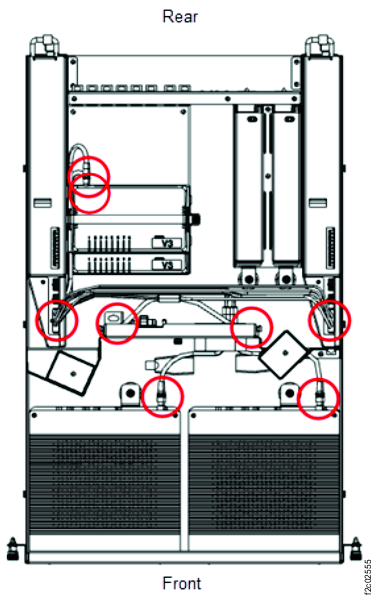
    Figure 1. Management enclosure (front)
    Front of Management enclosure (Model 983)
  4. Disconnect the cable FRU from the J3 connector on both power supplies (E31 and E32). See Figure 2.
    Important: DO NOT DISCONNECT the RPC card power cables that are connected to the power supply J1 and J2 connectors. The RPC cards must remain powered on during this procedure.
    Figure 2. Management enclosure power supply locations
    Management enclosure power supply locations
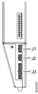
  5. Disconnect the cable management enclosure 12V power distribution cable from the remaining connections. See Figure 3 and Figure 4.
    Figure 3. Management enclosure locations (Model 983)
    Management enclosure locations
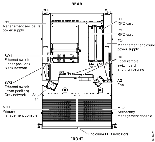
    Figure 4. Management enclosure 12V power distribution cable connections
    Management enclosure cable, power supplies to fans, MCs, SWs eight connectors
  6. Remove the cable FRU. Remove the cable retention as needed.

Install the cable FRU

Procedure

  1. Route the new cable FRU to all connectors. Do not connect the cable until instructed.
  2. Connect the cable FRU to the fan (A1, A2) cable connector brackets, management consoles (MC1, MC2), and Ethernet switches (SW1, SW2). See Figure 3 and Figure 4.
  3. Connect the cable FRU to the J3 connector of both power supplies (E31 and E32).
  4. Reinstall any cable retention that was removed.
  5. Ensure that the two fan assemblies are connected to the cable FRU.
  6. Log in to each management enclosure and ensure that each is functional.
  7. The preceding steps create one or more new open serviceable events that are related to FRUs in the management enclosure.

    Display open serviceable events. Are there any new related ones?

    • Yes, go to step 8.
    • No, go to step 9.
  8. Review the FRU list in the new unexpected serviceable event.
    • If the FRU list is related to the replaced cable, ensure it was installed correctly. Then, go to step 9.
    • If the FRU list is not related to the replaced cable, repair this unexpected error after the original serviceable event repair is complete. Go to step 9.
  9. Return the management enclosure to the operating position.
    1. Install the cover and fasten the two rear captive thumbscrews.
    2. Slide the management enclosure fully in and tighten the left and right captive thumb screws.
  10. Return to the procedure that sent you here.