MAP2880 Loss of AC input to a single UPS (Model 983)

The UPS reports a loss of line-cord AC input. This loss can also be caused by a UPS overcurrent that trips the input circuit breaker.

MAP2880 Section-1

About this task

This MAP assumes that only one UPS in this storage facility reported a loss of line cord AC input.

Note: If power is restored to the UPS, a new serviceable event with reference code BE19BDA1 is created. Then, this new serviceable event is automatically closed along with the original serviceable event. In this case, no further action is necessary.

Procedure

  1. Look for a serviceable event that contains reference code BE19BDA1. If the serviceable event exists, this serviceable event is in the Closed state. Note the following information:
    1. The location code (E61 or E62) of the affected UPS.
    2. The last reported time of the serviceable event.

    Did you find a serviceable event that contains reference code BE19BDA1?

  2. Review the serviceable event that referred to this MAP. Note the following information:
    1. The location of the UPS that reported the loss of line cord AC
    2. The last reported time of the serviceable event
    3. The current state of the serviceable event (Open or Closed)

    Is the serviceable event that referred to MAP2880 Loss of AC input to a single UPS (Model 983) now in the Closed state?

MAP2880 Section-2

Procedure

  1. Using the location for the UPS FRU in the serviceable event, locate the UPS that reported the loss of line cord AC. See Figure 1.
    Figure 1. Locations for the storage controller module in the rack
    Storage controller module (enclosures shown)

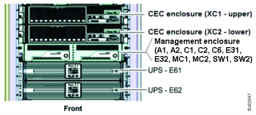
  2. At the rear of the UPS, observe the push-button input breaker above the J10 power input connector. See Figure 2.
    Is it tripped?
    Figure 2. Locations of the UPS (rear)
    Location codes for the UPS (Model 983), rear view
  3. Check the input power cable.
    1. Is the input power cable connected to the J10 connector? See Figure 2.
      • Yes. Go to step 3.b.
      • No. Connect the cable. Go to step 3.b.
    2. Is the other end of the input power cable connected to the UPS power source?
      Note: The UPS power source can either be internal to the rack or external to the rack.
        • Yes. Go to step 4.
        • No. Connect the cable. Go to step 4.
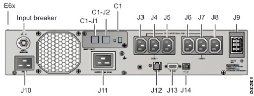
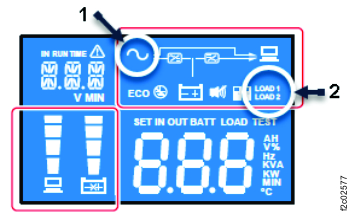
  4. Wait one minute and then observe the UPS control panel. See Figure 3.

    Are the LOAD1 Callout label 2 and LOAD2 Callout label 2 LCD indicators lit?

    • Yes. The UPS is in the power on state. Exit this MAP and close the serviceable event that reported the loss of AC input.
    • No. Go to step 5.
    Figure 3. UPS control panel indicators
    UPS control panel with indexes
  5. Determine whether the UPS mainline power cable power source has power.
    1. Use any available visual indicators or use an IBM approved multi-meter to measure for proper voltage.
    2. Work with the customer to ensure that the power source (internal or external to the rack) is providing power to the UPS mainline power cable connector.
      • If the power source is failing, work with the customer to have it fixed.
      • If the failure is the mainline power cable or UPS, exit this MAP and replace the failing FRU. When the repair is complete, ensure the UPS AC icon is on. Then close any related open serviceable events.