MAP6580 Customer Ethernet connection problem

Use this procedure to analyze problems with management console (HMC) Ethernet connection to the customer LAN.

About this task

Use MAP7000 Entry point For storage facility private network problems to analyze problems with the DS8000 private network.

MAP6580 Section-2, xSeries 335, 336, or 3550

Procedure

  1. Is the customer able to connect to the HMC through the customer network?
  2. At the rear of the management console server, verify that the customer Ethernet cable is properly connected to the customer network connector (eth2). See Figure 1 (X335 server) or Figure 2 (X336 server) or Figure 3 (X3550 server).

    Did you find and correct the problem with the Ethernet cable?

    • Yes, ask the customer to retry the operation. If problems still persist, then go to the next step.
    • No, go to the next step.
    Figure 1. Ethernet connectors on the rear of the X335 management console server
    Management console rear view with Ethernet locations
    Figure 2. Ethernet connectors on the rear of the X336 management console server
    X336 management console Ethernet ports
    Figure 3. Ethernet connectors X3550 management console server (rear view)
    X3550 management console server (front view)
  3. At the rear of the management console server, observe the link status LED at the customer network connector (eth2). See Figure 4 (X335 server) or Figure 5 (X336 server) or Figure 6 (X3550 server). The LED is lit when the Ethernet controller receives a LINK pulse from the hub.

    Is the link status LED lit?

    Figure 4. LEDs on the rear of the X335 management console server
    LEDs on the rear of the X335 MC server
    Figure 5. LEDs on the rear of the X336 management console server
    LEDs on the rear of the X336 MC server
    Figure 6. LEDs on the rear of the X3550 management console server
    LEDs on the rear of the X3550 management console server
  4. Move the customer Ethernet cable from connector PI-C1-T1 (eth0) to P1-C2-T2 (eth1). See Figure 1 (X335 server) or Figure 2 (X336 server) or Figure 3 (X3550 server).

    Is the link status LED on P1-C2-T2 (eth1) lit?

    • Yes, move the customer Ethernet cable back to P1-C1-T1 (eth0) and go to step 7.
    • No, go to the next step.
  5. Work with the customer to check the following conditions:
    1. The other end of the Ethernet cable is plugged correctly to the customer-supplied switch or hub.
    2. The switch or hub is functioning correctly.
    3. The port on the hub is working correctly. (Ask the customer to move the cable to a different port and retry the operation.)
    4. The customer supplied Ethernet cable is working correctly. (Swap the cable and verify whether the problem still exists.)
  6. Did you resolve the problem with the customer network or cable?
  7. Reset the customer Ethernet port on the HMC. Changes to network settings take effect immediately; therefore, the network does not need to be restarted. A logon screen appears, and the HMC requires the CE to log in again.
  8. Observe the link status LED at the customer network port (eth2). See Figure 4 (X335 server) or Figure 5 (X336 server) or Figure 6 (X3550 server).

    Is the link status LED lit?

MAP6580 Section-3, Laptop management console

Procedure

  1. Can the customer connect to the HMC through the customer network?
  2. Ensure that the customer network cable is properly connected to the customer network connector at the rear of the rack. See Figure 7 and Figure 8.
    Figure 7. ThinkPad laptop customer modem and Ethernet connectors, rear of rack
    Laptop rear connector view
    Note: Ethernet connector and modem connector might be reversed on some racks. Both connectors are at the rear of the rack, to the right of the Ethernet switches, below the bottom storage enclosure air baffle.
    Figure 8. Customer modem and Ethernet connectors, DS8870 All Flash, rear of rack
    Ethernet switch tray locations (Model 961 rack version 2 rear)
  3. Ensure the built-in Ethernet extender cable from the rear of rack is properly connected to the customer Ethernet connector (eth2) on the laptop.
    • W500: eth2 is on left side of laptop. See Figure 9.
    • T510, T520, T530: eth2 is on right side of laptop. See Figure 10.
    • T540: eth2 is on the rear of the laptop. See Callout label 1 Figure 11.
    Figure 9. Customer eth2 Ethernet connector on laptop (rear view)
    Customer eth2 Ethernet connector on laptop (rear view)
    Figure 10. ThinkPad T510, T520, and T530 USB and RJ45 network connection ports
    ThinkPad T510 USB ad RJ45 network connection ports
    Figure 11. ThinkPad T540 laptop unit cable connections (left and rear)
    ThinkPad T540 laptop unit cable connections (left and rear)

    Did you find and correct the problem with the Ethernet extender cable between the rear of the rack and the laptop?

    • Yes, ask the customer to retry the operation. If problems still persist, then go to the next step.
    • No, go to the next step.
  4. Observe the amber link status LED next to the customer's network connector (eth2). The LED is lit when the Ethernet controller receives a LINK pulse from the hub.

    Is the link status LED lit?

  5. Work with the customer to check the following conditions:
    1. The other end of the Ethernet cable is plugged correctly to the customer-supplied switch or hub.
    2. The switch or hub is functioning correctly.
    3. The port on the hub is working correctly. (Ask the customer to move the cable to a different port and retry the operation.)
    4. The customer-supplied Ethernet cable is working correctly. (Swap the cable and verify whether the problem still exists.)
  6. Did you resolve the problem with the customer's network or cable?
  7. Reset the customer's Ethernet port on the HMC:
    1. From the navigation area, click HMC Management.
    2. In the right work area, go to the Operations section and click Change Network Settings. The Change Network Settings window opens.
    3. Click the LAN adapters tab and select eth2.
    4. Click Details to verify the settings.
    5. Click OK when the Request returns.
  8. Observe the link status LED at the customer network port (eth2). Is the link status LED lit?

MAP6580 Section-4

Procedure

  1. Reset the customer Ethernet port on the HMC. Changes to network settings take effect immediately; therefore, the network does not need to be restarted. A logon screen appears, and the HMC requires the CE to log in again.
  2. Ask the customer to retry the operation. Does the problem still occur?
    • Yes, go to the next step.
    • No, the problem is resolved.
  3. Verify that the network settings are correct.
    1. On the HMC, select: HMC Management > Operations > Change Network Settings.
    2. Use the customer supplied customization worksheets to check that the settings are correct for eth2.
    3. For management consoles with second customer LAN connection (eth1), use the customer supplied customization worksheets to check that the settings are correct for eth1.
    CAUTION:
    Do not change network settings for the other Ethernet ports.
  4. Did you find the problem with the network settings?
    • Yes, change the settings to the appropriate values and ask the customer to retry the operation. If problems still persist, then go to the next step. Note: This change requires that the HMC is restarted. Ensure that the customer is not accessing the management console through the ESSNI interface.
    • No, go to the next step.
  5. Test the connectivity from the HMC to the customer network.
    1. Ask the customer to supply an IP address for a working device that can be contacted on their network. (If the HMC is connected through a gateway or firewall, try that first.)
    2. On the HMC, select: HMC Management > Operations > Test Network Connectivity.
    3. Enter the customer supplied IP address in the pop-up window for the ping utility and click OK.
    4. Allow 10 seconds and then click Stop.
      • Successful communication results in a series of messages to indicate that data was received.
      • Unsuccessful communication results in no data being received or a timeout message.
  6. Was the communication test successful?
  7. Ask the customer to attempt to 'ping' the HMC IP address from a computer on their network. If the HMC connects through a gateway or firewall, then attempt to ping the HMC from a device on the same side of the gateway as the HMC. Was the 'ping' successful?
    • Yes, go to step 9.
    • No, go to the next step.
  8. Verify the following conditions:
    1. The network settings were correct on the customization worksheets.
    2. If a gateway or firewall is being used, then ensure that the ping test still fails on the HMC side of the gateway.
    3. If not problem was identified, then go to MAP6580 Section-5.
  9. Ask the customer to 'ping' the HMC host name. Was the 'ping' test successful?
    • Yes, there does not appear to be an HMC network connectivity problem.
      • If the customer is experiencing problems with ESSNI, CLI, or other applications, go to Start here and look for the symptoms described.
      • Refer to the ThinkPad® T500 and W500 (15.4-inch widescreen) Hardware Maintenance Manual on the IBM® DS8000 series Service Documents CDROM to test the Ethernet controller for eth2.
      • In the appropriate maintenance manual for the management console server, refer to the Ethernet controller troubleshooting chart. The manual is on the IBM DS8000 series Service Documents CDROM:
        • xSeries 335 Type 8676, Type 8830 Hardware Maintenance Manual and Troubleshooting Guide
        • xSeries 336 Type 1879 and Type 8837 Hardware Maintenance Manual and Troubleshooting Guide
        • IBM System x3550 Type 7978 and 1913 Problem Determination and Service Guide
        • ThinkPad® T500 and W500 (15.4-inch widescreen) Hardware Maintenance Manual
        • ThinkPad T510, T510i, and W510 Hardware Maintenance Manual
        • Hardware Maintenance Manual ThinkPad® T520, T520i, and W520
        • Hardware Maintenance Manual ThinkPad® T530, T530i, and W530
        • Hardware Maintenance Manual ThinkPad® T540p and W540
      • If the customer is still experiencing problems in accessing the HMC, contact your next level of support for assistance.
    • No, there appears to be a problem with resolution of the HMC host name.
      • Verify that the host name was entered correctly in step 3.
      • Ask the customer to check that their DNS server is configured and working correctly.

MAP6580 Section-5

Procedure

  1. Run the Ethernet diagnostics. Go to MAP6530 Testing the management console. Return here when the test is completed.
    Notes:
    1. This task requires that the HMC is restarted. Ensure that the customer is not accessing the HMC through the ESSNI interface.
    2. A wrap plug (FRU 60G3981) is used with the diagnostic tests.
  2. Did the MAP6530 Testing the management console diagnostics find an error with the Ethernet controller?
    • Yes, go to MAP6580 Section-6.
    • No, apparently there is a network problem that is external to the HMC. Work with the customer or next level of support to resolve the problem.

MAP6580 Section-6

Procedure

  1. If the management console is an xSeries, replace the system board (HMC planar) in the management console server. Refer to the service replaceable units in the appropriate maintenance manual for the management console server. The manual is on the IBM DS8000 series Service Documents CDROM:
    • xSeries 335 Type 8676, Type 8830 Hardware Maintenance Manual and Troubleshooting Guide
    • xSeries 336 Type 1879 and Type 8837 Hardware Maintenance Manual and Troubleshooting Guide
    • IBM System x3550 Type 7978 and 1913 Problem Determination and Service Guide
  2. If the management console is a laptop, replace the laptop. See Exchange the laptop unit (T520, T530, T540).
  3. If the management console is a Model 98x management console, replace the management console.
  4. Ask the customer to retry the operation. If problems still persist, contact your next level of support.

MAP6580 Section-7, Model 98x (not 983) management console

Procedure

  1. Can the customer connect to the HMC through the customer network?
  2. Ensure that the customer network cable is properly connected to the customer network connector at the rear right side of the rack. See Figure 12, Table 1, and Figure 13.
    Note: Ethernet connection Callout label 1 is for management console 1 (MC 1). Ethernet connection Callout label 2 is for management console 2 (MC2).

    For management consoles with second customer LAN connection (eth1), refer to Table 1.

    Figure 12. Model 98x management console customer modem (where applicable) and Ethernet connectors, rear of rack
    Model 98x management console customer modem (where applicable) and Ethernet connectors, rear of rack
    Table 1. Small form factor management console customer network connections (rear)
    Index Management console connection or component
    1 Ethernet eth2 (customer), management console 1 (MC 1)
    2 Ethernet eth2 (customer), management console 2 (MC 2)
    3 Ethernet eth1 (second customer LAN connection, if used), management console 1 (MC 1)
    4 Ethernet eth1 (second customer LAN connection, if used), management console 2 (MC 2)
  3. Ensure that the built-in Ethernet extender cable from the rear of rack is properly connected to the customer Ethernet connector (eth2) on the management console; see Callout label 2 in Figure 13.
    For management consoles with second customer LAN connection (eth1), ensure that the built-in USB extender cable from the rear of the rack is properly connected to the USB connector on the management console; see Callout label 6 in Figure 13.
    Figure 13. Model 98x management console rear view customer network interface
    Model 98x management console cable connections (rear)

    Did you find and correct the problem with the USB or Ethernet extender cable between the rear of the rack and the management console?

    • Yes, ask the customer to retry the operation. If problems still persist, then go to the next step.
    • No, go to the next step.
  4. Observe the amber link status LED next to the customer's network connector (eth2) (Callout label 2, Figure 13). The LED is lit when the Ethernet controller receives a LINK pulse from the hub.
    For management consoles with second customer LAN connection (eth1), observe the 100/ACT LED indicator (Figure 14). The LED is lit (solid or flashing) when the link is active.
    Is the link status LED lit?
    Figure 14. USB Ethernet adapter LED indicators
    USB Ethernet adapter LED indicators
  5. Work with the customer to check the following conditions:
    1. The other end of the Ethernet cable is plugged correctly to the customer-supplied switch or hub.
    2. The switch or hub is functioning correctly.
    3. The port on the hub is working correctly. (Ask the customer to move the cable to a different port and retry the operation.)
    4. The customer-supplied Ethernet cable is working correctly. (Swap the cable and verify whether the problem still exists.)
  6. Did you resolve the problem with the customer's network or cable?

MAP6580 Section-8, Model 983 management console

Procedure

  1. Can the customer connect to the HMC through the customer network?
  2. Locate the Ethernet cable coupler that the customer network cable is connected to.
    1. There is a bundle of four Ethernet cables that extend out of the rear right end of the management enclosure cable management arm. See Figure 15, green circle.
    2. Each Ethernet cable has a cable coupler for the customer cable connection.
    3. In Table 2, use the Connections at Customer End columns to identify the specific coupler connection for the customer reported failure.
    Figure 15. Model 983 management console customer network connectors, rear of rack
    Model 983 management console customer modem (where applicable) and Ethernet connectors, rear of rack
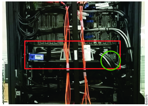
    Table 2. Customer Ethernet connections to management consoles
    Ethernet cable connections to management console end Connections at management enclosure rear cable coupler Ethernet cable connections to customer couplers

    Connections at customer end

    Management console, connection Management console connection port and type Uses USB to Ethernet adapter?   Cable with label Cable color Boot color
    MC 1, primary eth2, direct No MC1-A HMC1 - eth2 Blue Purple
    MC 2, primary eth2, direct No MC2-A HMC2 - eth2 Red Purple
    MC 1, secondary eth1, USB adapter Yes MC1-B HMC1 - eth1 Blue Green
    MC 2, secondary eth1, USB adapter Yes MC2-B HMC2 - eth1 Red Green
    Figure 16. Ethernet connections, management console ports to rear of management enclosure
    Management enclosure Ethernet cables (Models 983)
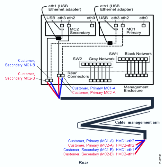
    Figure 17. Model 98x management console rear view customer network interface
    Model 98x management console cable connections (rear)
  3. Is the customer network cable connected to the proper Ethernet cable coupler?
    • Yes, go to step 5.
    • No, connect the customer network cable to the proper Ethernet cable coupler. Go to step 4.
  4. Have the customer ensure that their network cables are connected at their end.
    Have the customer test their connection to the management console.

    Is it still failing?

    • Yes, go to the next step.
    • No, the problem is fixed. Exit this MAP and close any related open serviceable events.
  5. At the front of the rack, slide the management enclosure out to the service position and remove the top cover. See Figure 18 and Figure 19.
    Note: The management enclosure is below the two CEC enclosures.
    1. Fully loosen the left and right captive thumb screws.
    2. Slide the management out fully so the sliding rails lock into place.
    3. At the rear of the top cover, fully loosen the left and right captive thumb screws.
    4. Slide the cover back until it lifts off.
    Figure 18. Front of Management enclosure (Model983)
    Front of Management enclosure (Model 983)
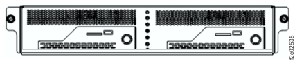
    Figure 19. Management enclosure locations (Model 983)
    Management enclosure locations
  6. Trace the communication path from the management console to the rear cable couplers. See Table 2, Figure 15, Figure 16, and Figure 17.

    Did you find and correct a cabling problem?

    • Yes, ask the customer to retry the operation. If problems still persist, then go to the next step.
    • No, go to the next step.
  7. Select the following choice that applies:
    • If you are repairing a primary connection to a management console eth2 port, the Ethernet path connects directly to the management console Ethernet port. Go to step 9.
    • If you are repairing a secondary connection to a management console eth1 port, the Ethernet path connects to a USB Ethernet adapter that connects to a management console USB port. Go to step 8.
  8. Locate the USB Ethernet adapter, it is directly connected to the management console. Observe the amber link status LED. See Figure 20. The LED is lit (solid or flashing) when the link is active.

    Is the link status LED lit?

    • Yes, go to MAP6580 Section-4.
    • No. Read the following note, then go to the next step.
    • Note: The USB Ethernet adapter might be failing. If the customer can test their cable and ensure that it is working at the management console end, the adapter LED should be lit. If it is not lit, the adapter can be hot plugged.
    Figure 20. USB Ethernet adapter LED indicators
    USB Ethernet adapter LED indicators
  9. Work with the customer to check the following conditions at their end of their Ethernet cable:
    1. The other end of the Ethernet cable is plugged correctly to the customer-supplied switch or hub.
    2. The switch or hub functions correctly.
    3. The port on the hub works correctly. If not, ask the customer to move the cable to a different port and retry the operation.
    4. The customer-supplied Ethernet cable works correctly. If not, swap the cable and verify whether the problem still exists.
  10. Did you resolve the problem with the customer's network or cable?