MAP7033 Private network isolation procedure 33
The Network Topology tool has been used to determine that one or both of the management consoles lost connectivity to an LPAR on a single CEC enclosure (one of the two processor complexes in a storage facility) through the Black network (eth0).
MAP7033 Section-1
Before you begin
Procedure
-
For rack model 983 only. At the front of the rack, slide the management enclosure out to the
service position and remove the top cover. See Figure 1.
Note: The management enclosure is below the two CEC enclosures.
- Fully loosen the left and right captive thumb screws.
- Slide the management out fully so the sliding rails lock into place.
- At the rear of the top cover, fully loosen the left and right captive thumb screws.
- Slide the cover back until it lifts off.
- When the service action is complete, reverse these steps.
Figure 1. Management enclosure (front)
-
Locate Ethernet switch SW2 (Figure 2 or Figure 3) in the storage facility that contains the affected LPAR.
Use the tables to determine the locations of the switch port, CEC port, and Ethernet cable that correspond to the failing service processor.
-
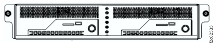
Locate Ethernet switch SW1 (Figure 2 or Figure 3) in the storage facility that contains the affected LPAR. Use Table 1, Table 2, Table 3,
Table 4, or Table 5 to determine the locations of the switch
port, CEC port, and Ethernet cable that correspond to the failing LPAR.
Table 1. Port locations (Model 941 and 951) LPAR LPAR port location SW1 port location SW2 port location SFxxxxxxxESS0x U789D.001.nnnnnnn-P1-C10-T1 (Upper CEC enclosure) T5 — SFxxxxxxxESS1x U789D.001.nnnnnnn-P1-C10-T1 (Lower CEC enclosure) T6 — SFxxxxxxxESS0x U789D.001.nnnnnnn-P1-C10-T2 (Upper CEC enclosure) — T5 SFxxxxxxxESS1x U789D.001.nnnnnnn-P1-C10-T2 (Lower CEC enclosure) — T6 Table 2. Port locations (Model 961) LPAR LPAR port location SW1 port location SW2 port location SFxxxxxxxESS0x U78AA.001.nnnnnnn-P1-C2-T1 (Upper CEC enclosure) T5 — SFxxxxxxxESS1x U78AA.001.nnnnnnn-P1-C2-T1 (Lower CEC enclosure) T6 — SFxxxxxxxESS0x U78AA.001.nnnnnnn-P1-C2-T2 (Upper CEC enclosure) — T5 SFxxxxxxxESS1x U78AA.001.nnnnnnn-P1-C2-T2 (Lower CEC enclosure) — T6 Table 3. Port locations (Models 980, 983, and 984) LPAR LPAR port location SW1 port location SW2 port location SFxxxxxxxESS01 U78CB.001.nnnnnnn-P1-C10-T1 (Upper CEC enclosure) T5 SFxxxxxxxESS11 U78CB.001.nnnnnnn-P1-C10-T1 (Lower CEC enclosure) T6 SFxxxxxxxESS01 U78CB.001.nnnnnnn-P1-C10-T2 (Upper CEC enclosure) T5 SFxxxxxxxESS11 U78CB.001.nnnnnnn-P1-C10-T2 (Lower CEC enclosure) T6 Table 4. Port locations (Models 981, 985, and 986) LPAR LPAR port location SW1 port location SW2 port location SFxxxxxxxESS01 U78C9.001.nnnnnnn-P1-C10-T1 (Upper CEC enclosure) T5 SFxxxxxxxESS11 U78C9.001.nnnnnnn-P1-C10-T1 (Lower CEC enclosure) T6 SFxxxxxxxESS01 U78C9.001.nnnnnnn-P1-C10-T2 (Upper CEC enclosure) T5 SFxxxxxxxESS11 U78C9.001.nnnnnnn-P1-C10-T2 (Lower CEC enclosure) T6 Table 5. Port locations (Models 982 and 988) LPAR LPAR port location SW1 port location SW2 port location SFxxxxxxxESS01 U78C7.001.nnnnnnn-P1-C11-T1 (Upper CEC enclosure) T5 SFxxxxxxxESS11 U78C7.001.nnnnnnn-P1-C11-T1 (Lower CEC enclosure) T6 SFxxxxxxxESS01 U78C7.001.nnnnnnn-P1-C11-T2 (Upper CEC enclosure) T5 SFxxxxxxxESS11 U78C7.001.nnnnnnn-P1-C11-T2 (Lower CEC enclosure) T6 Figure 2. 8-port Ethernet switch port designations (SW1, SW2-Tx) Model 941, Model 951, and Model 961 
Figure 3. Located on the rear, righthand side of Rack-1, the 8-port Ethernet switch port designations (Models 98x, not 983)
Figure 4. Located inside the management enclosure, the 8-port Ethernet switch port designations. (Model 983)
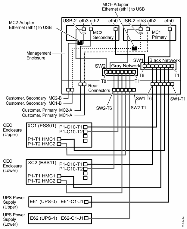
Figure 5. Locations, management enclosure (Model 983)
- Check the Ethernet port "link" LED on the switch
and CEC Ethernet ports identified in step 3.
Is the link LED on solid?
- Use the Network topology tool as described
in MAP7001 Using the network topology tool to check whether the problem is resolved.
Is the network problem resolved?
- Yes, go to MAP1500 Ending a service action to close the serviceable event, save the network topology, and ensure that good subsystem status.
- No, continue with the next step.
- Is there
an unused port on the same switch?
- Yes, go to the next step.
- No, this can occur only on an 8-port switch. Temporarily unplug the cable from port T8 (T1 for model 98x), and then continue to the next step.Note: For models 9A2 and 9B2, this might cause a new serviceable event to be opened for Ethernet communications from the second LPAR on this CEC enclosure. After this cable is reconnected in the following step, you can close that serviceable event.
- Move the cable plugged into the port located in step 3 to an unused port on the Ethernet switch.
- Use the Network topology tool as described in MAP7001 Using the network topology tool to check whether the problem is resolved.
Is the network problem resolved?
- Yes, this indicates a faulty port on the Ethernet switch. Go to MAP7033 Section-2.
- No, continue with the next step.
- Move the cables that were swapped in the prior steps back to their original positions.
- Temporarily install a new Ethernet cable in place of the existing cable between the faulty LPAR Ethernet port and the Ethernet switch port determined earlier.
- Use the Network topology tool as described in MAP7001 Using the network topology tool to check whether the problem is resolved.
Is the network problem resolved?
- Yes, this indicates a faulty Ethernet cable. Go to MAP7033 Section-3 to replace the cable.
- No, go to MAP7033 Section-4 to reset the LPAR and retest.
MAP7033 Section-2
About this task
Procedure
- Go to Exchanging parts to replace the SW1 Ethernet switch.
- Return here when you have replaced the Ethernet switch.
MAP7033 Section-3
About this task
Procedure
- Replace the faulty Ethernet cable between the Ethernet switch and the LPAR Ethernet port.
- Verify the fix using the Network topology tool as described
in MAP7001 Using the network topology tool. Is the network problem resolved?
- Yes, go to MAP1500 Ending a service action to close the serviceable event, save the network topology, and ensure good subsystem status.
- No, reseat the cable again and repeat this step. If the problem persists, it appears that you installed a faulty Ethernet cable or have a problem with the LPAR or CEC hardware. Replace the cable again. If replacing the cable again does not resolve the problem, go to MAP7033 Section-4 to reset the LPAR or replace the CEC hardware.
MAP7033 Section-4
About this task
LPAR is activating or resuming, RM on target is not yet running. No further actions are allowed. Refresh to see status.and status:
IML Incomplete(255)
Procedure
-
Quiesce the LPAR that is failing. Use Storage Facility
Management > storage facility > SF image > LPAR > > Change/Show LPAR State > Quiesce
LPAR.
If unable to quiesce the LPAR, proceed to step 5, "Identify the FRU that contains the failing Ethernet port...". -
Deactivate the LPAR that is failing. Use Storage Facility
Management > storage facility > SF image > LPAR > Change/Show LPAR state > Shutdown LPAR.
If unable to shutdown the LPAR, proceed to step 5, "Identify the FRU that contains the failing Ethernet port...". -
Activate the LPAR that is failing. Use Storage Facility
Management > storage facility > SF image > LPAR > Change/Show LPAR state > Activate LPAR.
If unable to activate the LPAR, proceed to step 5, "Identify the FRU that contains the failing Ethernet port..." - Use the Network topology tool as described in MAP7001 Using the network topology tool to check whether communication with
the LPAR is now working. Is communication with the LPAR now working?
- Yes, continue with step 8.
- No, continue with the next step.
-
Identify the FRU that contains the failing Ethernet port using Table 6, Table 7, Table 8,
Table 9, or Table 10.
Table 6. LPAR and FRU association (Model 941 and 951) LPAR FRU SFxxxxxxxESS01 U789D.001.nnnnnnn-P1-C10 (Upper CEC enclosure VPD pass-through card) SFxxxxxxxESS11 U789D.001.nnnnnnn-P1-C10 (Lower CEC enclosure VPD pass-through card) SFxxxxxxxESS01 U789D.001.nnnnnnn-P1 (Upper CEC enclosure I/O backplane) SFxxxxxxxESS11 U789D.001.nnnnnnn-P1 (Lower CEC enclosure I/O backplane) Note: The Ethernet adapter logic for CEC models 941 and 951 is located on the CEC enclosure VPD pass-through card and the CEC enclosure I/O backplane. At this point, you have isolated the issue to one or both of these two CEC components. Network surveillance is not designed to isolate between these two FRUs.Replacement of the CEC enclosure VPD pass-through card involves removing nearly all CEC components, similar to replacing the CEC enclosure I/O backplane. Because of the time required to separately replace these two FRUs, it is strongly recommended that the CEC enclosure VPD pass-through card and the CEC enclosure I/O backplane be replaced in the same service action. The only situation where the CEC enclosure VPD pass-through card is the more likely FRU is when only one Ethernet port is failing and its green link LED (the lower LED) is off. In this one case, it would be feasible to replace only the CEC enclosure VPD pass-through card.
Table 7. LPAR and FRU association (Model 961) LPAR FRU SFxxxxxxxESS01 U78AA.001.nnnnnnn-P1-C2 (Upper CEC enclosure Ethernet two port card) SFxxxxxxxESS11 U78AA.001.nnnnnnn-P1-C2 (Lower CEC enclosure Ethernet two port card) SFxxxxxxxESS01 U78AA.001.nnnnnnn-P1 (Upper CEC enclosure system backplane) SFxxxxxxxESS11 U78AA.001.nnnnnnn-P1 (Lower CEC enclosure system backplane) Table 8. LPAR and FRU association (Models 980 and 984) LPAR FRU SFxxxxxxxESS01 U78CB.001.nnnnnnn-P1-C10 (Upper CEC enclosure Ethernet ports card ) SFxxxxxxxESS11 U78CB.001.nnnnnnn-P1-C10 (Lower CEC enclosure Ethernet ports card) SFxxxxxxxESS01 U78CB.001.nnnnnnn-P1 (Upper CEC enclosure system backplane) SFxxxxxxxESS11 U78CB.001.nnnnnnn-P1 (Lower CEC enclosure system backplane) Table 9. LPAR and FRU association (Models 981, 985, and 986) LPAR FRU SFxxxxxxxESS01 U78C9.001.nnnnnnn-P1-C10 (Upper CEC enclosure Ethernet ports card ) SFxxxxxxxESS11 U78C9.001.nnnnnnn-P1-C10 (Lower CEC enclosure Ethernet ports card) SFxxxxxxxESS01 U78C9.001.nnnnnnn-P1 (Upper CEC enclosure system backplane) SFxxxxxxxESS11 U78C9.001.nnnnnnn-P1 (Lower CEC enclosure system backplane) Table 10. LPAR and FRU association (Models 982 and 988) LPAR FRU SFxxxxxxxESS01 U78C7.001.nnnnnnn-P1-C11 (Upper CEC enclosure Ethernet adapter) SFxxxxxxxESS11 U78C7.001.nnnnnnn-P1-C11 (Lower CEC enclosure Ethernet adapter) SFxxxxxxxESS01 U78C7.001.nnnnnnn-P1 (Upper CEC enclosure system backplane) SFxxxxxxxESS11 U78C7.001.nnnnnnn-P1 (Lower CEC enclosure system backplane) - If there is an open serviceable event calling the selected FRU, use the serviceable event to replace the FRU. If the FRU cannot be replaced using a serviceable event, then use Storage Facility Management > storage facility > Exchange Parts to select and replace the FRU.
- Use the Network topology tool as described in MAP7001 Using the network topology tool to check whether communication with
the LPAR is now working. Is communication with the LPAR now working?
- Yes, continue with step 9.
- No, contact your next level of support.
- Resume the LPAR. Use Storage Facility Management > storage facility > SF image > LPAR > Resume LPAR.
- Go to MAP1500 Ending a service action to close the serviceable event, save then network topology, and ensure good subsystem status.