Exchange the I/O enclosure (2U) midplane assembly

About this task

Icon for electrostatic discharge wrist strapUse approved ESD procedures to prevent damage.

Attention:
  • This procedure is not a stand-alone procedure. Customer disruption and damage to the hardware might occur when microcode and power boundaries are not in the proper conditions for this service action.
  • If a serviceable event FRU repair directed you to this procedure, the microcode and power boundaries are already set.
  • If a serviceable event FRU repair did not direct you to this procedure, see MAP1230 Replace a FRU without using a serviceable event.
Notes:
  • All the cables and FRUs to be removed must be uniquely identified so they can be reinstalled correctly.
  • If an installed earthquake resistance kit prevents you from accessing this FRU, refer to MAP1600.

Remove the I/O enclosure (2U) midplane assembly

Before you begin

Important: Every power supply, fan assembly, adapter card, cable, and customer Fibre Host cable must be returned to its original location to prevent an extended service time.

Procedure

  1. To locate this FRU, take one of the following actions and then return here and continue to replace the FRU:
    • If this FRU has a FRU identify indicator, use the FRU identify indicator, which is listed in MAP1240 Locating FRUs by using identify indicators. If not, use the location code.
      Note: There might be cases where the FRU failure or fencing conditions prevent the FRU LED indicator from being lit even if the FRU has power.
    • Use the location code, which is listed in MAP1245 Finding FRUs by using location codes.
    • If there is no FRU identify indicator or location code, you were sent here by an isolation MAP or symbolic FRU procedure. Use the information in that procedure and the figures in this procedure to locate the proper part to exchange.
  2. Most, but not all, FRUs have identify indicators. Use the flashing amber or solid blue FRU identify indicators to ensure that you are working on the correct enclosure or FRU.
  3. At the front of the I/O enclosure, remove the front bezel by first removing the two screws.
  4. At the front of the I/O enclosure, unfasten each power supply hook-and-loop fastener and then unplug the power cables to the E1 and E2 power supplies. See Figure 1.
    Figure 1. I/O enclosure (2U) locations (front) (Model 983)
    I/O enclosure (2U) locations (front) (model 983)
  5. Remove both power supplies. Press the locking tab to the left to release each power supply.
  6. Remove both fan assemblies. Press the locking tab to the left to release each fan assembly.
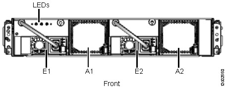
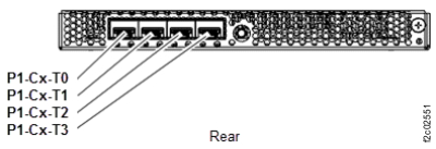
  7. At the rear of the I/O enclosure, ensure that all connected cables are properly labeled. See Figure 2.
    Note: Ensure that the customer host cables that are connected to the Fibre Channel adapters in Slots C3, C4, C5, C6 are labeled; the customer might not have labeled them.
    Figure 2. Location codes, I/O enclosure (2U) (rear) (model 983)
    I/O enclosure (2U) locations (front) (model 983)
  8. Disconnect the power cables from the E1 and E2 connectors at the rear of the I/O enclosure. See Figure 2.
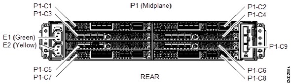
  9. Remove the I/O enclosure (2U) adapter (PCN).
    1. Ensure the two PCN (Power Control Network) cables (C9-T1, C9-T2) are properly labeled and then disconnect them. See Figure 3.
    2. Unlatch the blue lever at the right of the card and then slide the card out of the enclosure.
    Figure 3. Location codes, I/O enclosure (2U) adapter (PCN)
    Location codes, I/O enclosure (2U) adapter (PCN)
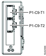
  10. Remove adapters and any slot baffles from slots C1 through C8. See Figure 2.
    1. The adapters have a combination of the connector types in Figure 4 and Figure 5.
    2. Ensure each cable to be disconnected is properly labeled. Then, disconnect each cable.
    3. Locate the jack screw at the far right of the adapter or slot baffle.
    4. Turn the jack screw counter-clockwise to unseat the adapter from the slot connector.
    5. Pull the adapter fully out of the slot.
    Figure 4. Location codes, I/O enclosure (2U) adapter (PCIe and SAS device)
    I/O enclosure (2U) adapter (generic)
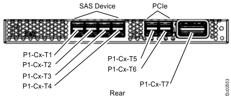
    Figure 5. Location codes, I/O enclosure (2U) adapter (Fibre Channel host)
    I/O enclosure (2U) adapter (Fibre Channel host)
  11. At the front of the rack, remove the I/O enclosure.
    1. Remove the two retaining screws that hold the enclosure to the rack rails.
    2. Slide the I/O enclosure out.

Install the I/O enclosure (2U) midplane assembly

Procedure

  1. Create the Machine Type Model Serial Number (MTMS) label for the new I/O enclosure (2U) midplane assembly.
    1. Locate the blank MTMS label in the FRU kit.
    2. Read the MTMS from the old enclosure assembly.
    3. Write the MTMS on the label.
    4. Apply the label on the new enclosure assembly in the same location as the old label.
  2. Slide the new enclosure assembly in the rack and secure it with both screws.
  3. At the rear of the enclosure, install and fasten in place the adapters and slot baffles in their original locations in slots C1 through C8. See Figure 2.
  4. At the rear of the enclosure, install the I/O enclosure (2U) adapter (PCN).
  5. At the rear of the enclosure, connect all the cables in their original locations. See Figure 2, Figure 3, Figure 4, and Figure 5.
    1. Connect the PCN (Power Control Network) cables (C9-T1, C9-T2).
    2. Connect the cables to the adapters in slots C1 through C8.
    3. Connect the power cables to the E1 and E2 connectors at the rear of the I/O enclosure
  6. At the front of the enclosure, install and fasten in place the power supplies and fan assemblies.
  7. Connect the power cables to the power supplies. Refasten the hook-and-loop fasteners.
  8. Did at least one power supply power-on and at least one fan assembly turn?
    • Yes, go to step 11.
    • No, go step 9.
  9. Neither power supply is powered on.
    1. Disconnect the power cable from each power supply.
    2. Ensure that each power supply is fully seated.
    3. Ensure that the other end of each power supply cable has power. If not, restore it.
    4. Reconnect the power cables. Refasten the hook-and-loop fasteners.
    5. If at least one power supply is powered-on, go to the next step.
    6. If neither power supply powered on, call the next level of support.
  10. At the front of the I/O enclosure, install the front bezel and secure it with two screws.
  11. Exit this service information center parts exchange procedure and return to the procedure that sent you here.