Exchange the DC-UPS DC supply unit (DSU)
Before you begin
CAUTION:
This assembly contains mechanical moving parts. Use care when
you service this assembly. (C025)
Use approved ESD procedures to prevent damage.
Attention:
- This procedure is not a stand-alone procedure. Customer disruption and damage to the hardware might occur when microcode and power boundaries are not in the proper conditions for this service action.
- If a serviceable event FRU repair directed you to this procedure, the microcode and power boundaries are already set.
- If a serviceable event FRU repair did not direct you to this procedure, see MAP1230 Replace a FRU without using a serviceable event.
Notes:
- All the cables and FRUs to be removed must be uniquely identified so they can be reinstalled correctly.
- If an installed earthquake resistance kit prevents you from accessing this FRU, refer to MAP1600.
Remove the DC-UPS DC supply unit (DSU)
Procedure
- Open the rear door.
- To locate this FRU, take one of the following actions and then return here and
continue to replace the FRU:
- If this FRU has a FRU identify indicator, use the FRU identify indicator,
which is listed in MAP1240 Locating FRUs by using identify indicators.
If not, use the location
code.Note: There might be cases where the FRU failure or fencing conditions prevent the FRU LED indicator from being lit even if the FRU has power.
- Use the location code, which is listed in MAP1245 Finding FRUs by using location codes.
- If there is no FRU identify indicator or location code, you were sent here by an isolation MAP or symbolic FRU procedure. Use the information in that procedure and the figures in this procedure to locate the proper part to exchange.
Figure 1. Models 980, 981, 982 base rack locations Note: Locations for models 980, 981, 982 are shown. DC-UPS locations are similar for models 98x and 8xE.
- If this FRU has a FRU identify indicator, use the FRU identify indicator,
which is listed in MAP1240 Locating FRUs by using identify indicators.
If not, use the location
code.
- Most, but not all, FRUs have identify indicators. Use the flashing amber or solid blue FRU identify indicators to ensure that you are working
on the correct enclosure or FRU.
- The
light path
identify LEDs are a hierarchy of LEDs that can identify the rack, enclosure, FRU, and even the FRU connector to which a cable is connected. - For more information, refer to MAP1240 Locating FRUs by using identify indicators.
- The
- Before proceeding, carefully study how the various cables are routed and secured.
- If needed, move more cables out of the way to allow easy access. Remove and then later restore cable ties as needed.
-
READ THIS ENTIRE STEP BEFORE YOU COMPLETE THE TASK.
- Confirm the location of the DC-UPS DSU being repaired. The DSU Service LED is flashing.
- On the DC-UPS DSU that is NOT being repaired, disconnect the cable from Ex-J9. For single-phase DSUs, J9 is located at the right side, just above the fan connector. For three-phase DSUs, J9 is located at the lower right corner above the main power connector. See Figure 2 or Figure 3.
- With the J9 cable disconnected, the DSU Service LED is now out on the DC-UPS being repaired.
Note: This confirmation protects the DC-UPS DSU that is not being repaired from any problem that is caused by the connector pins at the other end of the cable accidentally contacting the frame ground.Figure 2. Location codes for the DC-UPS (Models 98x, single-phase power) (rear)
Figure 3. Location codes for the DC-UPS (Models 98x, three-phase power) (rear)
- Have the customer remove power to the DC-UPS DSU being
repaired.
- Instruct the customer to turn off the circuit breaker
that supplies mainline ac voltage to the power receptacle for the DC-UPS DSU you are
repairing. Attention: Use lockout and tagout procedures as defined in the Electrical Safety for IBM® Customer Engineers.
-
Observe the rear of the DC-UPS DSU.
Is the LOCAL AC LED
(Figure 4 or Figure 5) indicator off?
- Yes, the customer removed power from the correct DC-UPS DSU. Continue with the next step.
- No, stop. The customer did not remove power from the correct DC-UPS DSU. Notify the customer. After you answer yes, go to the next step.
- Instruct the customer to turn off the circuit breaker
that supplies mainline ac voltage to the power receptacle for the DC-UPS DSU you are
repairing.
-
At the DC-UPS DSU being repaired, set the CB1
mainline switch to Off (down). See Figure 2 or Figure 3. This is the DC-UPS DSU which still has the
signal cable that is attached at Ex-J9.
Figure 4. LEDs on the DC-UPS DC supply unit (DSU) (Models 98x, single-phase power) (rear)
Figure 5. LEDs on the DC-UPS DC Supply Unit (DSU) (Models 98x, three-phase power) (rear)
- For three-phase power, go to step 14. For single-phase power, continue to the next step.
-
Behind the DC-UPS DSU, single-phase, loosen the screws
Figure 6 that secure the power cable bracket to
the frame.
-
If a safety cover is present, unfasten the screw
that
secures the safety cover
to the power cable bracket. Remove the cover. See Figure 6.
-
At the DC-UPS DSU, twist the lock ring
counterclockwise to release the mainline power cable. Disconnect the cable and slide it to the rear
to release the bracket from the screws. See Figure 6 and Figure 2.
Figure 6. Power cable bracket and safety cover 
- Go to step 15.
- At the DC-UPS DSU being repaired (three-phase), disconnect the mainline power cable. Push the two release levers at the side of power connector J14. See Figure 3.
- Slide the mainline power cable out of the way to allow the DC-UPS to be removed.
-
At the DC-UPS DSU being repaired, remove the
power safety cover.
- Single-phase power: remove the two screws, then remove the two halves of the cover.
- Three-phase power: loosen the two screws, slide the cover up and remove the cover.
-
At the DC-UPS DSU being repaired,
disconnect the DSU-to-DSU power cables from J3-1 and J3-2 (single-phase, see Figure 2), or from J3-1, J3-2, and J3-3
(three-phase, see Figure 3).
WARNING: High voltage is present at the recessed contacts of the shielded connectors on the DSU-to-DSU power cables.Note: If a J3-1, J3-2, or J3-3 cable connector does not release, check the following.
Each connector has two release latches that are interconnected by a plastic tab. If that tab breaks, you need to release both latches. - At the DC-UPS DSU being repaired, disconnect the remaining cables.
- Locate the green and yellow ground cable to the left of the mainline power connector. Disconnect the green and yellow ground cable at the rack end.
- At the front of the rack, remove the BSM set cover
(if present) from the BSM set enclosure. Loosen the screws
at both sides to remove. Figure 7. BSM set enclosure cover (Models 98x and 8xE, single-phase power) (front)
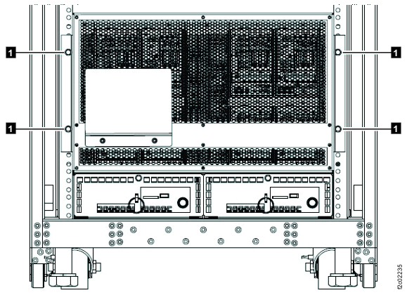
Note: BSM set enclosure cover for single-phase power configuration shown, enclosure cover for three-phase power is similar. - Gently slide the primary battery service module 1 inch
(2.54 cm) out of its enclosure so it undocks from the DC-UPS.
-
At the front of the rack, remove the retaining screw
(Figure 8 or Figure 9) at the top of the
primary battery service module in the DC-UPS being repaired. See Figure 10 or Figure 11.
- Do not disconnect the power cable from primary battery
service module connector J20
.
Figure 8. Battery service module (BSM) set for Models 98x, single-phase power, (front) 
Figure 9. Battery service module (BSM) set (Models 98x, three-phase power) (front) 
Figure 10. Battery service module (BSM) set locations (Models 98x single-phase power) (front) 
Figure 11. Battery service module (BSM) set locations (Models 98x, three-phase power) (front) 
-
At the front of the rack, remove the retaining screw
- For three-phase power, go to step 26. For single-phase power, continue to the next step.
- At the rear of the rack, unscrew the two screws that secure the DC-UPS DSU to the sheet metal chassis.
- Remove the DC-UPS DSU.
- Pull on the upper handle.
- Support the bottom with your other hand.
- Remove the DC-UPS DSU from the rack.
- Go to Install the DC-UPS DC supply unit (DSU).
-
At the rear of the rack, remove the upper and lower retaining brackets from the three-phase
DC-UPS DSU being repaired.
- Unfasten the upper retaining bracket by removing the two screws from the DSU handle and the two screws from the side of the bracket.
- Lift the upper retaining bracket up and remove the bracket.
- Unfasten the lower retaining bracket by removing the two screws from the DSU handle and the two screws from the side of the bracket.
- Pivot the bracket toward the center of the rack (away from the side rails) and remove the bracket.
-
Remove the upper section of the DC-UPS DSU.
- Pull on the upper handle, and slide the upper section toward the rear of the rack.
- Support the bottom of the upper section with your other hand.
- Separate the upper section from the lower section, and remove the upper section from the rack.
-
Remove the lower section of the DC-UPS DSU.
- Pull on the lower handle.
- Support the bottom with your other hand.
- Remove the lower section from the rack.
- Go to Compare the new and old DC-UPS DC supply unit (DSU) input phase selection settings.
Compare the new and old DC-UPS DC supply unit (DSU) input phase selection settings
About this task
Procedure
-
Determine the input phase selection settings for the old DC-UPS DSU.
- Refer to Figure 12 and Figure 13.
- Determine the power type: Three-phase low voltage (200 - 240 V), three-phase high voltage (380 - 415 V), or single-phase (200 - 240 V). Observe the P12, P13 connections.
Figure 12. DC-UPS input phase selection 
Figure 13. DC-UPS input phase selection label location 
-
Are the new DC-UPS input phase selections P12, P13 cable connections set the same as the old
DC-UPS?
- Yes, go to Install the DC-UPS DC supply unit (DSU).
- No, go to the next step.
-
On the new DC-UPS DSU, do the following:
- Loosen the thumbscrew and open the DC-UPS input phase selection cover.
- Reconnect the P12 and P13 cables to match those cables on the old DC-UPS DSU.
- Close the DC-UPS phase selection settings cover and tighten the thumbscrew.
- Go to Install the DC-UPS DC supply unit (DSU).
Install the DC-UPS DC supply unit (DSU)
Procedure
- For three-phase power, go to step 4. For single-phase power, continue to the next step.
- Install the DC-UPS DSU.
- Ensure that the CB1 mainline switch is Off (down).
- Slide the DC-UPS in.
- Ensure that the two screws are securely tightened.
- Go to step 11.
- Transfer any filler plugs from J1-1, J1-2, or J1-3; and J2-1, J2-2, or J2-3 on the old three-phase DC-UPS DSU to the same locations on the new DC-UPS DSU. See Figure 3.
-
Transfer the jumper plug from J5 on the old three-phase DC-UPS DSU to J5 on the new three-phase
DC-UPS DSU. See Figure 3.
Note: The DC-UPS will not power on if the jumper is not plugged in to J5.
-
If the new DC-UPS DSU does not have a ground cable, transfer the ground cable from the old
DC-UPS DSU. When connecting the ground cable to the DC-UPS DSU, the installation order is:
- Star washer (against DSU chassis)
- Ground cable lug
- Standard washer
- Split washer
- Nut
- If the new DC-UPS DSU does not have pull tabs attached to the release levers at the sides of power connector J14, transfer the pull tabs from the old DC-UPS DSU. These pull tabs are a piece of hook and loop fastener or similar material.
-
Install the lower section of the three-phase DC-UPS DSU.
- Ensure the CB1 main line switch is Off (down).
- Slide the lower section in.
- Install the upper section of the DC-UPS DSU. Ensure that the serial number on the upper section matches the lower section.
-
Install the upper and lower retaining brackets on the DC-UPS DSU being repaired.
- Insert the lower retaining bracket tab into the slot in the center rail. Pivot the bracket toward the side of the rack.
- Fasten the two screws at the side of the bracket and the two screws in the DSU handle.
- Place the upper bracket on top of the DSU. Ensure the tab at the rear of the bracket engages at the top rear of the DSU chassis.
- Fasten the two screws at the side of the bracket and insert the two screws into the DSU handle. Leave the handle screw loose (you will tighten them when you install the safety cover).
-
Connect the green and yellow ground cable. Ensure that the washers are properly installed.
Refer to the other DC-UPS if needed.
To connect the ground cable to the system frame, the installation order is:
- Star washer (against frame)
- Ground cable lug
- Screw
- If the new DC-UPS did not include the fan assembly on the upper section, transfer the fan assembly from the original DC-UPS DSU. The fan assembly is held in place by the three screws.
- Connect the fan assembly cable to the Ex-J4 connector. See Figure 2 or Figure 3.
-
At the front of the rack, insert the primary battery service module. Install the
retaining screw
at the top of the battery service module. See Figure 8 or Figure 9.
- Install the BSM set enclosure cover (if removed).
-
At the rear of the DC-UPS DSU being
repaired, connect the DSU-to-DSU power cables
J3-1 and J3-2 (single-phase) or J3-1, J3-2, and J3-3 (three-phase).
See Figure 2 or Figure 3. Take care that the recessed
contacts of the connectors do not touch other metal objects such as the DC-UPS chassis.
WARNING: High voltage is present at the recessed contacts of the shielded connectors on the DSU-to-DSU power cables.
- At the DC-UPS DSU being
repaired, connect all other cables EXCEPT:
- J9 communication
- Mainline power cable
See Table 1.Table 1. DC-UPS DSU cable connections Location Connection Remarks J1-1, J1-2, J1-3
(J1-3 for 3-phase only)DSU DDM power Connect now J2-1, J2-2, J2-3
(J2-3 for 3-phase only)DSU main power Connect now J3-1, J3-2, J3-3
(J3-3 for 3-phase only)DSU partner power Connected in an earlier step J4 DSU fan power Connect now J5 DSU jumper Connect now J6 DSU to RPC C1 Connect now J7 DSU to RPC C2 Connect now J8 DSU to Rack ID card C5 (expansion rack only) Connect now (expansion rack only) J9 DSU to DSU communication Connect later, when directed J14 Mainline power Connect later, when directed - At the DC-UPS DSU being serviced, ensure that the CB1 mainline switch is Off (down).
-
At the DC-UPS DSU being repaired, reinstall the power safety cover.
- Single-phase power: insert the tabs into the slot in the DSU fan assembly, then install the brackets and fasten with screws.
- Three-phase power: slide the cover down and into place, and tighten the two screws.
- Route the mainline power cable into position behind the
DC-UPS. Attention: Confirm that the cable is not powered before you connect it.
- For three-phase power, go to step 25. For single-phase power, go to the next step.
-
Connect the mainline power cable to the DC-UPS DSU
(single-phase). See Figure 2.
-
Position the keyholes in the power cable bracket over the screws
and slide
the cable forward to the input connector. See Figure 6.
- Twist the lock ring clockwise to secure the connector.
-
Position the keyholes in the power cable bracket over the screws
-
Secure the power cable bracket and safety cover (if present) on the mainline power cable. See
Figure 6.
-
Tighten the screws
to secure the bracket to the frame.
-
Install the cover
and secure with the screw
.
-
Tighten the screws
- Go to step 26.
- Connect the mainline power cable to the DC-UPS DSU (three-phase) and ensure that both latches are secure.
- Instruct the customer to turn on the mainline circuit breaker that supplies mainline AC voltage to the power receptacle for the DC-UPS you are repairing.
-
Set the CB1 mainline switch to On (up).
Note: The DDM and MAIN LEDs might flash for a short time. You check them again in a later step.
- At the DC-UPS DSU being
repaired, verify that the LOCAL AC LED is lit solid.
If the LOCAL AC LED is not lit, recheck the following conditions:
- The mainline power cable is securely connected
- The correct mainline circuit breaker is turned on
- The CB1 mainline switch is turned on
If the LOCAL AC LED is still not lit after you rechecked the items above, do not continue. Contact your next level of support.
-
At the DC-UPS DSU being repaired,
verify the DSU MAIN output (J2-1, J2-2, J2-3) and DDM output
(J1-1, J1-2, J1-3) LEDs are lit solid.
If the DSU MAIN and DDM output LEDs are not lit solid, do not continue. Contact your next level of support.
- At the DC-UPS DSU being repaired, connect the Ex-J9 DSU to DSU communication cable (right side, just above the fan connector for single-phase; lower right corner above the main power connector for three-phase). See Figure 2 or Figure 3.
-
At the DC-UPS DSU REMAINING IN CUSTOMER USE,
connect the Ex-J9 DSU to DSU communication cable at the bottom right.
See Figure 2 or
Figure 3.
Note: At the DC-UPS DSU being repaired, the DSU Service amber LED should flash. If the LED is not flashing, you can still continue the repair.
- If you are repairing Rack-2, 3, 4, or 5, observe
the rack operator panel LEDs on the upper left of the rack front cover.
See Figure 14.
- The upper green LED
is for the left (facing rear) DC-UPS (E1). - The lower green LED
is for the right (facing rear) DC-UPS (E2).
Is the green LED for the DC-UPS that you repaired lit solid or slow flashing?
- Yes, continue at the next step.
- No, ensure that the cable is properly connected to the DC-UPS DSU J8 connector.
The cable can be hot-plugged.
If the LED is now lit, continue at the next step.
If the LED is not lit, the possible failing FRUs are:- Rack identity card to DC-UPS cable
- Rack identity card
- Rack identity card to operator panel LED assembly cable
- Rack operator panel LED assembly
Note: E1-J8 (Left DC-UPS DSU, from rear) cable goes to C5-J1 (rack identity card).
E2-J8 (Right DC-UPS DSU, from rear) cable goes to C5-J2 (rack identity card).
C5-J3 (rack identity card) cable goes to rack operator panel LED assembly.
Figure 14. Rack operator LEDs on upper left of rack front cover 
- The upper green LED
- Close the rear door.
- Exit this service information center parts exchange procedure and return to the procedure that sent you here.
) flashes when it works. See