Exchange the direct power junction assembly (PJA)

Before you begin

The direct PJA provides power from an I/O enclosure to one or more microbays.

Icon for electrostatic discharge wrist strapUse approved ESD procedures to prevent damage.

Attention:
  • This procedure is not a stand-alone procedure. Customer disruption and damage to the hardware might occur when microcode and power boundaries are not in the proper conditions for this service action.
  • If a serviceable event FRU repair directed you to this procedure, the microcode and power boundaries are already set.
  • If a serviceable event FRU repair did not direct you to this procedure, see MAP1230 Replace a FRU without using a serviceable event.
Notes:
  • All the cables and FRUs to be removed must be uniquely identified so they can be reinstalled correctly.
  • If an installed earthquake resistance kit prevents you from accessing this FRU, refer to MAP1600.
DANGER
Hazardous voltage, current, or energy levels are present inside of a component to which this label is attached. (L001)
Safety label L001

Remove the direct power junction assembly (PJA)

Procedure

  1. To locate this FRU, take one of the following actions and then return here and continue to replace the FRU:
    • If this FRU has a FRU identify indicator, use the FRU identify indicator, which is listed in MAP1240 Locating FRUs by using identify indicators. If not, use the location code.
      Note: There might be cases where the FRU failure or fencing conditions prevent the FRU LED indicator from being lit even if the FRU has power.
    • Use the location code, which is listed in MAP1245 Finding FRUs by using location codes.
    • If there is no FRU identify indicator or location code, you were sent here by an isolation MAP or symbolic FRU procedure. Use the information in that procedure and the figures in this procedure to locate the proper part to exchange.
  2. Most, but not all, FRUs have identify indicators. Use the flashing amber or solid blue FRU identify indicators to ensure that you are working on the correct enclosure or FRU.
  3. Disconnect the cables in the following order:
    1. Input cables J10
    2. Output cables J11, J12
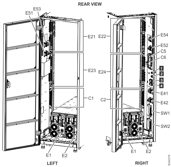
    Figure 1. Direct power junction assembly (direct PJA) locations (models 984, 84E, 985, 85E, 986, 86E, 988, 88E)
    Model 98x direct power junction assembly (direct PJA) locations - E51, E52, E53, and E54
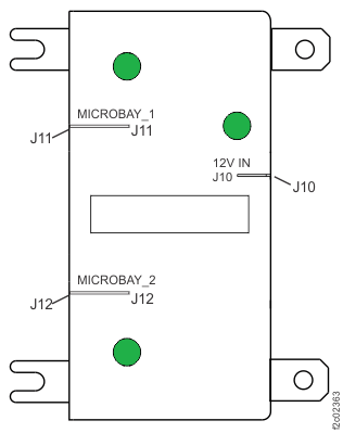
    Figure 2. Model 984, 985, 986, 988 base rack locations
    Note: Rack-1 shown. PJAs E51, E52, E53, and E54 can also be present in Rack-2. DC-UPS locations are similar for models 98x and 8xE.
    Model 984, 985, 986, 988 base rack locations
  4. Remove the power junction assembly.
    1. Loosen the retaining bracket fastener.
    2. Slide the upper portion of the retaining bracket up and remove the assembly.

Replace the direct power junction assembly (PJA)

Procedure

  1. Replace the power junction assembly.
    1. Position the assembly on the lower portion of the retaining bracket.
    2. Secure the assembly with the upper portion of the retaining bracket. Secure the fastener.
  2. Connect the cables in the following order:
    1. Output cables J11, J12
    2. Input cable J10
  3. Observe the PJA LEDs.
  4. Exit this service information center parts exchange procedure and return to the procedure that sent you here.