Exchange the I/O enclosure power supply to 208 VDC bus bar cable
Before you begin
 Use approved ESD procedures to prevent damage.
Attention:
- This procedure is not a stand-alone procedure. Customer disruption and damage to the hardware might occur when microcode and power boundaries are not in the proper conditions for this service action.
- If a serviceable event FRU repair directed you to this procedure, the microcode and power boundaries are already set.
- If a serviceable event FRU repair did not direct you to this procedure, see MAP1230 Replace a FRU without using a serviceable event.
Notes:
- All the cables and FRUs to be removed must be uniquely identified so they can be reinstalled correctly.
- If an installed earthquake resistance kit prevents you from accessing this FRU, refer to MAP1600.
Remove the I/O enclosure power supply to 208 VDC bus bar cable
About this task
Note: The
I/O enclosure must be fully removed from the rack for this procedure.
Procedure
- At the front of the rack, unplug the power input cable
 to both power supplies in the I/O
enclosure. See Figure 1.
to both power supplies in the I/O
enclosure. See Figure 1.
Figure 1. I/O enclosure power supply plugs 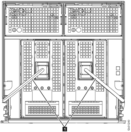
- Remove both power supplies.
- Remove the I/O power supply retention bracket by removing the screws on either side
of the bracket
 . See Figure 2.
 Figure 2. I/O enclosure power supply retention bracket 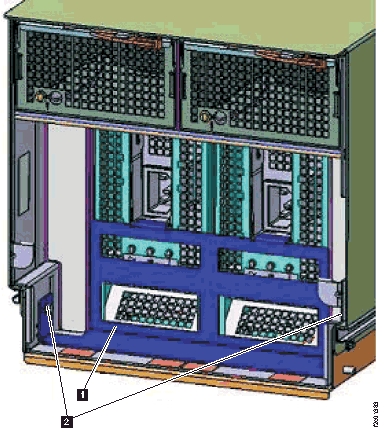
- Push down on the red release button beneath the input power connector.
See Figure 3.
Figure 3. I/O enclosure power supply, input power connector release button 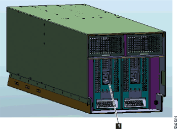
- Remove the I/O power supply retention bracket
- Remove both fan assemblies.
See Figure 4.
- Unlatch the fan release lever in the upper right corner of the fan.
Then, use it to pull the fan assembly straight out from the I/O enclosure.
Figure 4. Removing the I/O enclosure fan 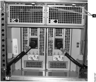
- Unlatch the fan release lever
-
At the rear of the rack, unplug all the cables (RIO
, SPCN , ID
 , FC-AL
  and customer host
  ). Ensure that the cables are labeled so they can be properly replugged. See Figure 5.
Figure 5. PCIe, SPCN, FC-AL, customer host cables 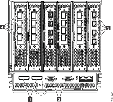
- Unplug the two black power cables from the 208 VDC bus
bars. From the rear of the rack (as
shown in Figure 6):
-
Trace both I/O power supply cables from the rear of the I/O enclosure to the 208 VDC secondary bus bars .
Note: There are two power cables that exit between the rear of the I/O enclosures. You might need to gently pull on the unplugged cable from the front of the I/O enclosure to ensure that you know which cable at the rear will be unplugged in the next substeps.
- Gently pull the blue retention bracket and then slide it to the side to allow
the cable to be unplugged.
- Unplug the black power cable from the bus bar connector .
Figure 6. I/O with power cables 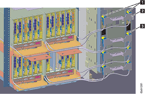
-
Trace both I/O power supply cables
- Remove the I/O enclosure chassis from the rack. See Figure 7.
- At the rear of the rack, remove the two hold down screws .
- Push the I/O enclosure forward towards the front of
the rack .
- At the front of the rack, pull the I/O enclosure out the front being careful to balance it when it is free of the rack.
- Place the I/O enclosure on a static free surface.
Figure 7. Remove the I/O enclosure chassis Note: Earlier rack model shown. I/O enclosure removal from Model 98x is similar.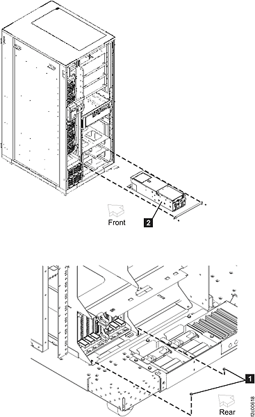
- At the rear of the rack, remove the two hold down screws
Install the I/O enclosure power supply to 208 VDC bus bar cable
Procedure
- Install the new power cable alongside the I/O enclosure.
- Slide the I/O enclosure back into the rack and install the two hold down screws.
- At the rear of the rack, connect all the cables to the I/O enclosure.
- At the front of the rack install the two power supplies. Ensure that the red latch beneath the input power connector is secure.
- Reinstall the I/O power supply retention bracket.
- Install and latch the two fans.
- Connect the two black power cables to the power supplies.
- Route and connect the power cables to the 208 VDC bus bars.
- At the bus bars, slide the blue retention bracket back in position.
- Reinstall the cable retention hardware.
- Exit this service information center parts exchange procedure and return to the procedure that sent you here.