Exchange the I/O enclosure device adapter card, SAS (flash)

Before you begin

Icon for electrostatic discharge wrist strapUse approved ESD procedures to prevent damage.

Attention:
  • This procedure is not a stand-alone procedure. Customer disruption and damage to the hardware might occur when microcode and power boundaries are not in the proper conditions for this service action.
  • If a serviceable event FRU repair directed you to this procedure, the microcode and power boundaries are already set.
  • If a serviceable event FRU repair did not direct you to this procedure, see MAP1230 Replace a FRU without using a serviceable event.
Notes:
  • All the cables and FRUs to be removed must be uniquely identified so they can be reinstalled correctly.
  • If an installed earthquake resistance kit prevents you from accessing this FRU, refer to MAP1600.

Remove the I/O enclosure device adapter card, SAS (flash)

Procedure

  1. To locate this FRU, take one of the following actions and then return here and continue to replace the FRU:
    • If this FRU has a FRU identify indicator, use the FRU identify indicator, which is listed in MAP1240 Locating FRUs by using identify indicators. If not, use the location code.
      Note: There might be cases where the FRU failure or fencing conditions prevent the FRU LED indicator from being lit even if the FRU has power.
    • Use the location code, which is listed in MAP1245 Finding FRUs by using location codes.
    • If there is no FRU identify indicator or location code, you were sent here by an isolation MAP or symbolic FRU procedure. Use the information in that procedure and the figures in this procedure to locate the proper part to exchange.
  2. Most, but not all, FRUs have identify indicators. Use the flashing amber or solid blue FRU identify indicators to ensure that you are working on the correct enclosure or FRU.
  3. At the rear of the rack, ensure that the SAS cables are properly labeled and disconnect them from the SAS ports in the card being removed.
  4. Unlatch the two blue levers Callout label 1 to the left of the card being removed. See Figure 1.
    Figure 1. I/O enclosure adapter retention levers
    I/O enclosure adapter retention levers
  5. Slide the card assembly out.

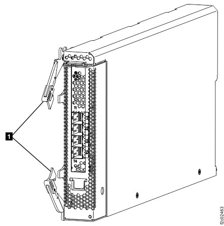
Install the I/O enclosure device adapter card, SAS (flash)

Procedure

  1. Slide the card in and use the two blue levers to latch it in place.
  2. For the SAS cables:
    • If you are doing a normal repair, use the labels to properly connect the SAS cables.
      • For SAS cables having labels which include the physical location code (example: R2-XI3-P1-C3-T2), see Figure 2.
      • For SAS cables having labels with only the three-character or four-character connection designators (example: 14A1), see Figure 3.
    • If you are installing the card as part of an MES, do not connect the SAS cables until directed later.
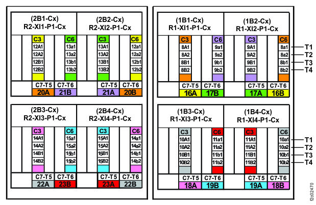
    Figure 2. Location codes for the device adapter card SAS ports
    Flash SAS cable connectors - Device adapter card, SAS (flash) (Cx-T1, T2, T3, T4)
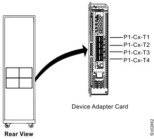
    Figure 3. Connection designators for the device adapter card SAS ports
    Connection designators for the device adapter card SAS ports
  3. Exit this service information center parts exchange procedure and return to the procedure that sent you here.