Exchange the PCIe cable, storage enclosure

Before you begin

Icon for electrostatic discharge wrist strapUse approved ESD procedures to prevent damage.

Attention:
  • This procedure is not a stand-alone procedure. Customer disruption and damage to the hardware might occur when microcode and power boundaries are not in the proper conditions for this service action.
  • If a serviceable event FRU repair directed you to this procedure, the microcode and power boundaries are already set.
  • If a serviceable event FRU repair did not direct you to this procedure, see MAP1230 Replace a FRU without using a serviceable event.
Notes:
  • All the cables and FRUs to be removed must be uniquely identified so they can be reinstalled correctly.
  • If an installed earthquake resistance kit prevents you from accessing this FRU, refer to MAP1600.

Remove the PCIe cable

Procedure

  1. To locate this FRU, take one of the following actions and then return here and continue to replace the FRU:
    • If this FRU has a FRU identify indicator, use the FRU identify indicator, which is listed in MAP1240 Locating FRUs by using identify indicators. If not, use the location code.
      Note: There might be cases where the FRU failure or fencing conditions prevent the FRU LED indicator from being lit even if the FRU has power.
    • Use the location code, which is listed in MAP1245 Finding FRUs by using location codes.
    • If there is no FRU identify indicator or location code, you were sent here by an isolation MAP or symbolic FRU procedure. Use the information in that procedure and the figures in this procedure to locate the proper part to exchange.
  2. Most, but not all, FRUs have identify indicators. Use the flashing amber or solid blue FRU identify indicators to ensure that you are working on the correct enclosure or FRU.
  3. Inspect both ends of the PCIe cable for proper connection. Use the figures at the end of this procedure to determine the location of both ends of the PCIe cable that is suspect.
  4. Is the PCIe cable properly connected at both ends?
    • Yes, go to the next step to replace the PCIe cable.
    • No, the PCIe cable is disconnected. There is no need to replace the PCIe cable. Instead, when directed to replace the FRU, you reconnect the cable and continue the repair.
  5. For model 982/98F, go to step 7. All other 98x models, go to the next step.
  6. At the rear of the rack on models other than 982 and 98F, disconnect the cable from the I/O enclosure PCIe and PCN card C7-T5 or C7-T6. Gently pull the release handle and then unplug the cable. Then, go to step 8. See Figure 1.
    Figure 1. I/O enclosure locations (rear) (models 98x, 8xE)
    I/O enclosure locations (rear) (models 98x)
  7. At the rear of rack models 982 and 98F, is the storage enclosure RAID controller card connected to I/O enclosure PCIe and PCN card C7-T5 or C7-T6?
    • Yes, gently pull the release handle and then unplug the cable. See Figure 1.
    • No, this PCIe cable is shipped as part of the I/O enclosure PCIe storage interface card and cable FRU kit. This cable cannot be ordered separately. To replace this cable, go to Exchange the I/O enclosure PCIe storage interface card.
  8. Remove the cable from the rack.
    Note: Applicable only for PCIe cables connected to I/O enclosure PCIe and PCN card C7-T5 or C7-T6 on model 98x.
    1. Trace the cable from the I/O enclosure PCIe and PCN card to the storage enclosure RAID controller card or to the microbay.
    2. DO NOT DISCONNECT the cable until you know that it is the other end of the cable that is already disconnected.
    3. Gently pull the release handle and then unplug the cable.
    4. Release the cable ties and remove the cable.

Install the PCIe cable

About this task

Note: Applicable only for PCIe cables connected to I/O enclosure PCIe and PCN card C7-T5 or C7-T6 on model 98x.

Procedure

  1. The new cable must have the proper location code labels applied to each end.
    Note: This cable has different connectors on each end. Confirm the I/O enclosure and storage enclosure ends before you apply labels.
    1. Observe the location code label on each end of the cable that you removed.
    2. Select the proper location code labels from the label sheet that is shipped with the new cable.
    3. Apply the labels to the new cable.
  2. Install the new PCIe cable.
    1. Route the cable neatly and use the cable ties to secure it.
    2. Connect both ends.
  3. Exit this service information center parts exchange procedure and return to the procedure that sent you here.
    Figure 2. Point-to-point cabling diagram for storage enclosure PCIe and FC-AL cables (Models 980, 98B, rear view, racks 1, 2)
    Point-to-point cabling diagram for storage enclosure PCIe and FC-AL cables (Models 980, 98B, rear view, racks 1, 2)
    Figure 3. Point-to-point cabling diagram for storage enclosure Flash PCIe / SAS cables (Models 980, 98B with HPFE Gen2) (rear view, racks 1 and 2)
    Note: Only HPFE Gen2 PCIe and SAS details are shown. HPFE Gen2 flash enclosure locations vary.
    Point-to-point cabling diagram for storage enclosure Flash PCIe / SAS cables (Models 980, 98B with HPFE Gen2) (rear view, racks 1 and 2)
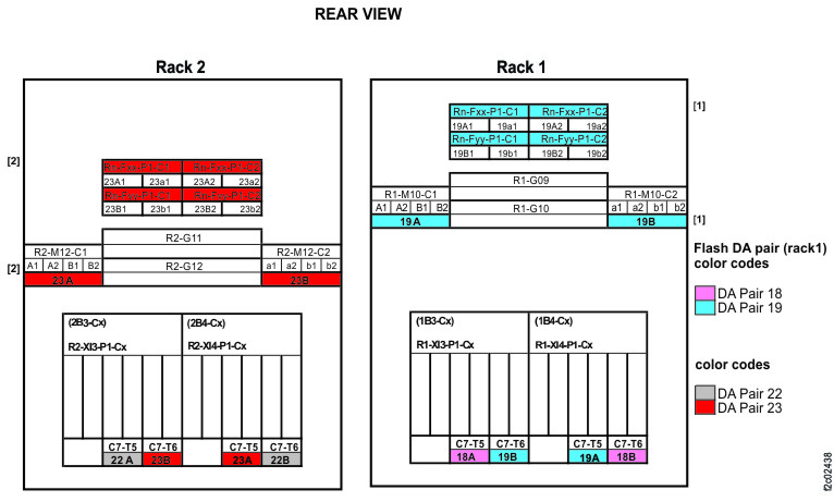
    Figure 4. Point-to-point cabling diagram for storage enclosure PCIe and FC-AL cables (Models 981, 98E, single-phase power, rear view, racks 1, 2)
    Point-to-point cabling diagram for storage enclosure PCIe and FC-AL cables (Models 981, 98E, rear view, racks 1, 2)
    Figure 5. Point-to-point cabling diagram for storage enclosure Flash PCIe / SAS cables (Models 981, 98E single-phase power with HPFE Gen2) (rear view, racks 1 and 2)
    Note: Only HPFE Gen2 PCIe and SAS details are shown. HPFE Gen2 flash enclosure locations vary.
    Point-to-point cabling diagram for storage enclosure Flash PCIe / SAS cables (Models 981, 98E single-phase power with HPFE Gen2) (rear view, racks 1 and 2)
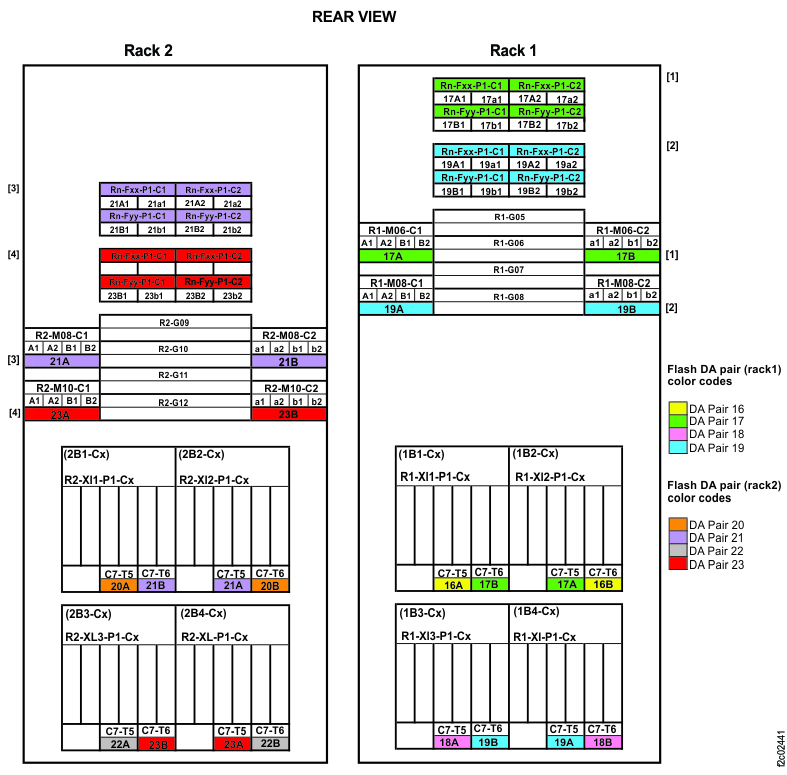
    Figure 6. Point-to-point cabling diagram for storage enclosure FC-AL and Flash PCIe cables (Models 981, 98E three-phase power, rear view, racks 1, 2)
    Point-to-point cabling diagram for storage enclosure FC-AL and Flash PCIe cables (Models 981, 98E three-phase power, rear view, racks 1, 2)
    Figure 7. Point-to-point cabling diagram for storage enclosure Flash PCIe / SAS cables (Models 981, 98E three-phase power with HPFE Gen2) (rear view, racks 1 and 2)
    Note: Only HPFE Gen2 PCIe and SAS details are shown. HPFE Gen2 flash enclosure locations vary.
    Point-to-point cabling diagram for storage enclosure Flash PCIe / SAS cables (Models 981, 98E three-phase power with HPFE Gen2) (rear view, racks 1 and 2)
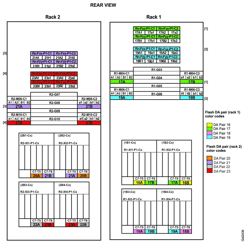
    Figure 8. Point-to-point cabling diagram for storage enclosure PCIe and FC-AL cables (Models 982, 98F, rear view, racks 1, 2)
    Point-to-point cabling diagram for storage enclosure Flash PCIe cables (Models 982, 98F, rear view, racks 1, 2)
    Figure 9. Point-to-point cabling diagram for storage enclosure FC-AL and Flash PCIe / SAS cables (Models 984, 84E, rear view, racks 1, 2)
    Point-to-point cabling diagram for storage enclosure FC-AL and Flash PCIe / SAS cables (Models 984, 84E, rear view, racks 1, 2)
    Figure 10. Point-to-point cabling diagram for storage enclosure Flash PCIe / SAS cables (Model 984 all-flash, rear view, rack 1)
    Point-to-point cabling diagram for storage enclosure Flash PCIe / SAS cables (Model 984 all-flash, rear view, rack 1)
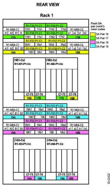
    Figure 11. Point-to-point cabling diagram for storage enclosure FC-AL and Flash PCIe / SAS cables (Models 985, 85E, single-phase power, rear view, racks 1, 2)
    Point-to-point cabling diagram for storage enclosure FC-AL and Flash PCIe / SAS cables (Models 985, 85E, single-phase power, rear view, racks 1, 2)
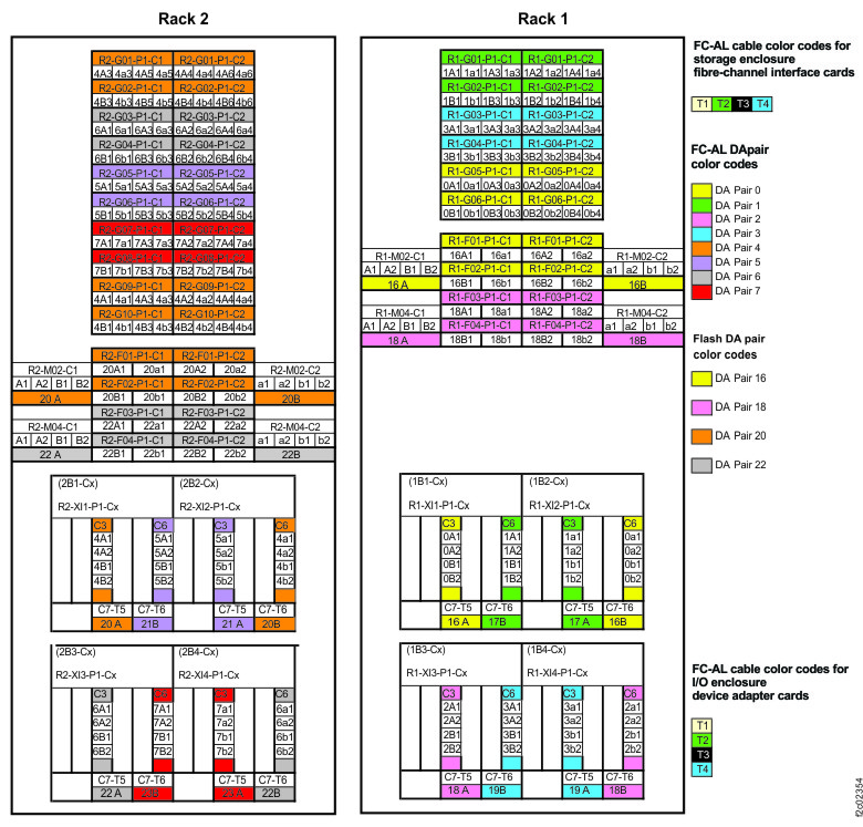
    Figure 12. Point-to-point cabling diagram for storage enclosure Flash PCIe / SAS cables (Models 985, 85E all-flash, single-phase power, rear view, racks 1, 2)
    Point-to-point cabling diagram for storage enclosure FC-AL and Flash PCIe / SAS cables (Models 985, 85E, single-phase power, rear view, racks 1, 2)
    Figure 13. Point-to-point cabling diagram for storage enclosure FC-AL and Flash PCIe / SAS cables (Models 986, 86E, three-phase power, rear view, racks 1, 2)
    Point-to-point cabling diagram for storage enclosure FC-AL and Flash PCIe / SAS cables (Models 986, 86E, three-phase power, rear view, racks 1, 2)
    Figure 14. Point-to-point cabling diagram for storage enclosure Flash PCIe / SAS cables (Models 986, 86E all-flash, three-phase power, rear view, racks 1, 2)
    Point-to-point cabling diagram for storage enclosure FC-AL and Flash PCIe / SAS cables (Models 985, 85E, single-phase power, rear view, racks 1, 2)
    Figure 15. Point-to-point cabling diagram for storage enclosure Flash PCIe / SAS cables (Models 988, 88E, rear view, racks 1, 2)
    Point-to-point cabling diagram for storage enclosure Flash PCIe / SAS cables (Models 988, 88E, rear view, racks 1, 2)