Exchange the power distribution unit (PDU)
Before you begin
 Use approved ESD procedures to prevent damage.
Attention:
- This procedure is not a stand-alone procedure. Customer disruption and damage to the hardware might occur when microcode and power boundaries are not in the proper conditions for this service action.
- If a serviceable event FRU repair directed you to this procedure, the microcode and power boundaries are already set.
- If a serviceable event FRU repair did not direct you to this procedure, see MAP1230 Replace a FRU without using a serviceable event.
Notes:
- All the cables and FRUs to be removed must be uniquely identified so they can be reinstalled correctly.
- If an installed earthquake resistance kit prevents you from accessing this FRU, refer to MAP1600.
DANGER
Hazardous
voltage, current, or energy levels are present inside of a component
to which this label is attached. (L001) 
Remove the power distribution unit (PDU)
Procedure
- To locate this FRU, do one of the following
and then return here and continue to replace the FRU:
- If this FRU has a FRU identify indicator,
use the FRU identify indicator, which is listed in MAP1240 Locating FRUs by using identify indicators. If not, use the location code.Note: There may be cases where the FRU failure or fencing conditions prevent the FRU LED indicator from being lit even if the FRU has power.
- Use the location code, which is listed in MAP1245 Finding FRUs by using location codes. (Figure 1)
- If there is no FRU identify indicator or location code, you were sent here by an isolation MAP or symbolic FRU procedure. Use the information in that procedure and the figures in this procedure to locate the proper part to exchange.
Figure 1. Models 980, 981, 982 base rack locations Locations for models 980, 981, 982 are shown. PDU locations are similar for expansion rack models 98x.
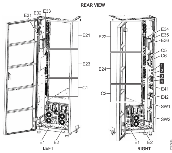
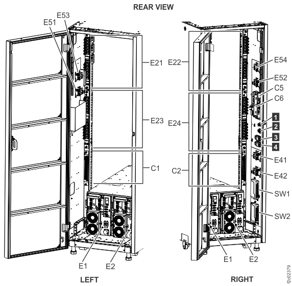
Figure 2. Models 984, 985, 986, 988 base rack locations Notes:- Locations for models 984, 985, 986, 988 are shown. PDU locations are similar for expansion rack models 8xE.
- Rack-1 shown. PJAs E51, E52, E53 and E54 can also be present in Rack-2.
- If this FRU has a FRU identify indicator,
use the FRU identify indicator, which is listed in MAP1240 Locating FRUs by using identify indicators. If not, use the location code.
-
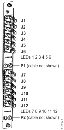
Disconnect the two PDU power input cable plugs P1 and P2 from the associated DC-UPS DSU power
connectors. See Table 1, Table 2, Table 3, Table 4, Table 5, and Table 6
for the connections that apply to the PDU you are replacing.
Attention: Ensure that you have the correct connectors before disconnecting.
Table 1. PDU-to-DC-UPS cabling overview Rack model(s) Rack number Refer to this table: 980, 98B
981, 98E single-phase
984, 84E
984 all-flash
985, 85E
985, 85E all-flashAll racks Table 2 982, 98F All racks Table 3 981, 98E three-phase
986, 86E
986, 86E all-flash
988, 88ERack-1 Table 4 981, 98E three-phase
986, 86E
986, 86E all-flash
988, 88ERack-2 Table 5 981, 98E three-phase
986, 86ERack-3, Rack-4, Rack-5 Table 6 988, 88E Rack-3 Table 6 Table 2. PDU-to-DC-UPS cabling - all racks (Models 980, 98B and Models 981, 98E with single-phase power; Models 984, 84E; Models 985, 85E) PDU port Connects to Connection description PDU group Note: For further guidance on theconnects to
locations in this table, refer to Rack power and cooling location codes.E21-P1 E1-J1-1 DC-UPS E1 (left), DDM source 1 Green E21-P2 E1-J1-2 DC-UPS E1 (left), DDM source 2 Green E22-P1 E2-J1-1 DC-UPS E2 (right), DDM source 1 Yellow E22-P2 E2-J1-2 DC-UPS E2 (right), DDM source 2 Yellow E23-P1 E1-J2-1 DC-UPS E1 (left), main source 1 Green E23-P2 E1-J2-2 DC-UPS E1 (left), main source 2 Green E24-P1 E2-J2-1 DC-UPS E2 (right), main source 1 Yellow E24-P2 E2-J2-2 DC-UPS E2 (right), main source 2 Yellow Table 3. PDU-to-DC-UPS cabling - all racks (Models 982, 98F) PDU port Connects to Connection description PDU group Note: For further guidance on theconnects to
locations in this table, refer to Rack power and cooling location codes.E21-P1 E1-J1-1 DC-UPS E1 (left), DDM source 1 Green E21-P2 E1-J2-1 DC-UPS E1 (left), main source 1 Green E22-P1 E2-J1-1 DC-UPS E2 (right), DDM source 1 Yellow E22-P2 E2-J2-1 DC-UPS E2 (right), main source 1 Yellow E23-P1 E1-J2-2 DC-UPS E1 (left), main source 2 Green E23-P2 E1-J2-3 DC-UPS E1 (left), main source 3 Green E24-P1 E2-J2-2 DC-UPS E2 (right), main source 2 Yellow E24-P2 E2-J2-3 DC-UPS E2 (right), main source 3 Yellow Table 4. PDU-to-DC-UPS cabling - Rack 1 (Models 981, 98E with three-phase power; Models 986, 86E; Models 988, 88E) PDU port Connects to Connection description PDU group Note: For further guidance on theconnects to
locations in this table, refer to Rack power and cooling location codes.E21-P1 E1-J1-1 DC-UPS E1 (left), DDM source 1 Green E21-P2 E1-J2-1 DC-UPS E1 (left), main source 1 Green E22-P1 E2-J1-1 DC-UPS E2 (right), DDM source 1 Yellow E22-P2 E2-J2-1 DC-UPS E2 (right), main source 1 Yellow E23-P1 E1-J2-2 DC-UPS E1 (left), main source 2 Green E23-P2 E1-J2-3 DC-UPS E1 (left), main source 3 Green E24-P1 E2-J2-2 DC-UPS E2 (right), main source 2 Yellow E24-P2 E2-J2-3 DC-UPS E2 (right), main source 3 Yellow Table 5. PDU-to-DC-UPS cabling - Rack 2 (Models 981, 98E with three-phase power; Models 986, 86E; Models 988, 88E) PDU port Connects to Connection description PDU group Note: For further guidance on theconnects to
locations in this table, refer to Rack power and cooling location codes.E21-P1 E1-J1-1 DC-UPS E1 (left), DDM source 1 Green E21-P2 E1-J1-2 DC-UPS E1 (left), DDM source 2 Green E22-P1 E2-J1-1 DC-UPS E2 (right), DDM source 1 Yellow E22-P2 E2-J1-2 DC-UPS E2 (right), DDM source 2 Yellow E23-P1 E1-J2-2 DC-UPS E1 (left), main source 2 Green E23-P2 E1-J2-3 DC-UPS E1 (left), main source 3 Green E24-P1 E2-J2-2 DC-UPS E2 (right), main source 2 Yellow E24-P2 E2-J2-3 DC-UPS E2 (right), main source 3 Yellow Table 6. PDU-to-DC-UPS cabling - Racks 3, 4, 5 (Models 981, 98E with three-phase power; Models 986, 86E); Rack 3 (Models 988, 88E) PDU port Connects to Connection description PDU group Note: For further guidance on theconnects to
locations in this table, refer to Rack power and cooling location codes.E21-P1 E1-J1-1 DC-UPS E1 (left), DDM source 1 Green E21-P2 E1-J2-1 DC-UPS E1 (left), main source 1 Green E22-P1 E2-J1-1 DC-UPS E2 (right), DDM source 1 Yellow E22-P2 E2-J2-1 DC-UPS E2 (right), main source 1 Yellow E23-P1 E1-J1-2 DC-UPS E1 (left), DDM source 2 Green E23-P2 E1-J1-3 DC-UPS E1 (left), DDM source 3 Green E24-P1 E2-J1-2 DC-UPS E2 (right), DDM source 2 Yellow E24-P2 E2-J1-3 DC-UPS E2 (right), DDM source 3 Yellow Figure 3. Locations for power distribution unit (PDU) connectors