Exchange the small form factor management console (Model 983)

Before you begin

Icon for electrostatic discharge wrist strapUse approved ESD procedures to prevent damage.

Attention:
  • This procedure is not a stand-alone procedure. Customer disruption and damage to the hardware might occur when microcode and power boundaries are not in the proper conditions for this service action.
  • If a serviceable event FRU repair directed you to this procedure, the microcode and power boundaries are already set.
  • If a serviceable event FRU repair did not direct you to this procedure, see MAP1230 Replace a FRU without using a serviceable event.
Notes:
  • All the cables and FRUs to be removed must be uniquely identified so they can be reinstalled correctly.
  • The entire management console is a single FRU. There are no parts to transfer between the old and new management console except for the rear cover plate.
  • The management console FRU is preinstalled with a base level of LIC. After the management console is exchanged, update the LIC bundle on the new management console by using the DVD drive. The DVD drive is stored in the document enclosure.

Remove the management console

Procedure

  1. If this storage facility does not have a second functioning management console, the customer cannot manage their storage while you do this procedure. Ensure that they are aware of this condition.
  2. Shut down the management console. For more information, see MAP6640 Shutting down, restarting, and logging off the management console.
  3. At the front of the rack, slide the management enclosure out to the service position and remove the top cover. See Figure 1.
    Note: The management enclosure is below the two CEC enclosures.
    1. Fully loosen the left and right captive thumb screws.
    2. Slide the management out fully so the sliding rails lock into place.
    3. At the rear of the top cover, fully loosen the left and right captive thumb screws.
    4. Slide the cover back until it lifts off.
    Figure 1. Management enclosure (front)
    Front of Management enclosure (Model 983)
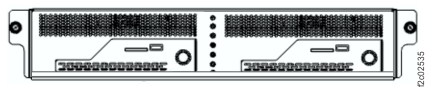
  4. Locate the management console, MC1 primary or MC2 secondary. See Figure 2.
    Figure 2. Locations for management enclosure
    Management enclosure locations
  5. At the rear of the management console, disconnect the power and communications cables. See Table 1 and Figure 3.
    Attention: Ensure that the power cable does not short to metal objects.
    Table 1. Small form factor management console connections
    Index Management console connection
    1 Power
    2 Ethernet eth3 (gray)
    3 Ethernet eth2 (customer)
    4 Ethernet eth0 (black)
    5 VGA to monitor cable couplers (Note 5.a)
    6 USB-2 to USB Ethernet adapter eth1 (second customer LAN connection, if present)
    7 USB-3 to keyboard cable couplers (Note 5.a)
    8 Not used
    9 Cover plate retaining screws (Note 5.b)
    Notes:
    1. Cables with couplers extend from the rear of the management enclosure cable management arm.
    2. Cover plate might not be present in all models.
    Figure 3. Model 98x management console cable connections (rear)
    Model 98x management console cable connections (rear)
  6. At the rear of the management console, near the VGA connector, loosen the single captive thumbscrew that fastens the management console tray to the enclosure. Lift the management console out of the management enclosure.
  7. Remove the mounting tray from the bottom of the management console. Remove the four screws.

Install the management console

Procedure

  1. Install the mounting tray on the new management console.
  2. If the management console that you are replacing contains an SDHC memory card in the media card reader slot (Callout label 3 Figure 4), transfer it to the new management console.
    Figure 4. Model 98x (not 983) management console (front). 983 management console similar.
    HMC management console (front)
  3. Install the management console in the management enclosure and secure it with the captive thumbscrew.
  4. Reconnect all cables except power and Ethernet eth3 and eth0. Power is connected in the next step. Ethernet eth0 and eth3 are connected after the network addresses are set on the new management console.
  5. Reconnect the power cable.
  6. Connect the portable DVD drive to the USB port  Callout label 2. See Figure 4.
  7. Update the management console LIC bundle as needed. Refer to MAP6200 Reloading the management console LIC bundle.
    Note: The LIC bundle is updated in all cases. The LIC bundle is reloaded only if the new management console does not boot, or when you directed by next level of support.
  8. Return the DVD drive to the storage location and return to this procedure.
  9. If you cannot access the management console after reloading the LIC bundle, go to MAP6060 Management console login and login problems at the management console server.
  10. Test the management console to ensure that all connections are functioning.
    1. Use the network topology tool to ensure that the gray and black private network connections are functioning. For more information, see MAP7001 Using the network topology tool.
    2. Display open serviceable events that need repair. If there are serviceable events that are related to this HMC, or private network timeout problems that were created when you replaced this unit, close them.
    3. Run the storage facility status (end of call) option. For more information, see MAP1100 View storage facility state (end of call).
    4. If the management console is configured for remote access, test it. Select Service Management > Manage Outbound Connectivity > Configure > Internet > Test. If the test fails, refer to MAP1301 Isolating Call Home/remote services failure.
    5. Ask the customer to test the access of the application or method that they use to connect to the Storage Manager application in the management console.
  11. Install the management enclosure cover. Slide the enclosure fully into the rack and secure it with the two thumbscrews. Return to the procedure that sent you here.