Completing the logical installation of the I/O enclosures
The steps in this procedure power-on and logically install each I/O enclosure pair. The lower pair will be logically installed first followed by the upper pair (if present).
Procedure
-
View the storage facility status. If any of the system check results
display as FAILED, view the details and refer to
MAP1100 View storage facility state (end of call). Before you continue the installation, all status fields should
display as PASSED.
Figure 1. Window: View Storage Facility State  Note: If the status for Large File Transfer (the tenth System Check Type status from the top) displays as FAILED, the remaining System Check Types below it cannot be displayed.
To display further details, select a row and click Details.
-
Select the condition that applies and corresponding action to take. Refer to Table 1, Figure 2, Figure 3, Figure 4, Figure 5,
Figure 6, Figure 7, and Figure 8.
Table 1. Rack-2 contents and actions Rack-2 contains these items Action to take 1 or more high-performance flash enclosures in locations R2-F01 through R2-F04
1 or more high-performance flash enclosures in locations R2-F05 through R2-F12 (Model 88E)Go to Routing and connecting the expansion rack SAS cables 0 high-performance flash enclosures in locations R2-F01 through R2-F04
1 or more high-performance flash enclosures in locations R2-F05 through R2-F12 (Model 88E)Important: If any enclosures are present in locations R2-F01 through R2-F04, see1 or more high-performance flash enclosures in locations R2-F01 through R2-F04
, in row 1 above.Go to Installing and testing the Rack-2 or Rack-3 high-performance flash enclosures 2 or more storage enclosures in locations R2-G01 through R2-G10 (single-phase Model 85E)
2 or more storage enclosures in locations R2-G03 through R2-G08 (three-phase Model 86E)
2 or more storage enclosures in locations R2-G01 through R2-G02 (Model 84E)
1 or more DA pairs in I/O enclosure slots R2-XIx-C3 and C6
0 or more high-performance flash enclosures in locations R2-F01 through R2-F04
Go to Installing and testing the Rack-2 I/O enclosure device adapter card pairs 2 or more storage enclosures in locations R2-G03 through R2-G10
0 DA pairs in Rack-2 I/O enclosure slots R2-XIx-C3 and C6
2 DA pairs in Rack-1 I/O enclosure slots R1-XIx-C3 and C6
0 or more high-performance flash enclosures in locations R2-F01 through R2-F04
(Model 84E only)
Go to Installing and testing the storage enclosures 0 storage enclosures in locations R2-G01 through R2-G10 (single-phase Model 85E)
0 storage enclosures in locations R2-G01 through R2-G08 (three-phase Model 86E)
0 DA pairs in I/O enclosure slots R2-XIx-C3 and C6
1 or more high-performance flash enclosures in locations R2-F01 through R2-F04
0 or more high-performance flash enclosures in locations R2-F05 through R2-F08 (Model 85E all-flash, Model 86E all-flash)
Go to Installing and testing the Rack-2 or Rack-3 high-performance flash enclosures 0 storage enclosures in locations R2-G01 through R2-G10 (single-phase Model 85E)
0 storage enclosures in locations R2-G01 through R2-G08 (three-phase Model 86E)
0 DA pairs in I/O enclosure slots R2-XIx-C3 and C6
0 high-performance flash enclosures in locations R2-F01 through R2-F04
1 or more host adapters in I/O enclosure slots R2-XIx-C1, C2, C4, or C5
Go to Installing and testing the Rack-2 I/O enclosures host adapter cards Figure 2. Location codes for device adapter and host adapter cards 
Figure 3. Rack 1-3 storage enclosure and I/O enclosure location codes (Models 988, 88E all-flash) (rear view) 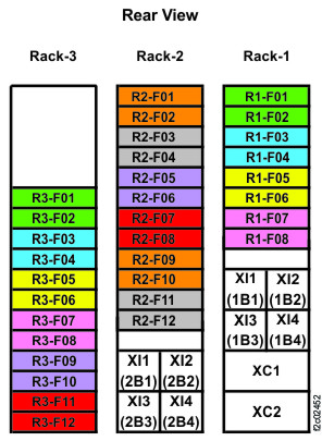
Figure 4. Rack 1-5 storage enclosure and I/O enclosure location codes (single-phase Models 985, 85E) (rear view) Note: High-performance flash enclosures are in Rack-1 and Rack-2.
Figure 5. Rack 1-2 storage enclosure and I/O enclosure location codes (single-phase Models 985, 85E all-flash) (rear view) 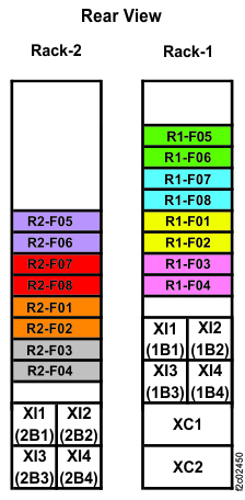
Figure 6. Rack 1-5 storage enclosure and I/O enclosure location codes (three-phase Models 986, 86E) (rear view) Note: High-performance flash enclosures are in Rack-1 and Rack-2.
Figure 7. Rack 1-2 storage enclosure and I/O enclosure location codes (three-phase Models 986, 86E all-flash) (rear view) 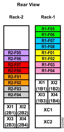
Figure 8. Rack 1-3 storage enclosure and I/O enclosure location codes (Models 984, 84E) (rear view) Note: High-performance flash enclosures are in Rack-1 and Rack-2.