MAP4963 Storage enclosure PCIe cable analysis
MAP4963 Section-1
About this task
- MAP4963
- Storage enclosure RAID controller card: U2107.D03.sssssss-P1-Cx or U1500.rBn.sssssss-P1-Cx
- Storage enclosure PCIe cable, or PCIe storage interface card and cable: U1500.rBn.sssssss-P1-Cx
- I/O enclosure PCIe/PCN card
- Various other FRUs or symbolic procedures, based on system reference code (SRC)
Procedure
-
A cable is disconnected or is connected to the wrong adapter.
SRC Action BE1E2546, BE382565, BE382573, BE382577, BE820180, BE820188
BE3825C3
Any other SRCs not specifically listed in this tableContinue the repair of this serviceable event with the next FRU on the FRU list (the affected storage enclosure RAID controller card).
When directed to exchange the FRU, instead reconnect the disconnected cable.Answer the following questions to continue the repair process with the next FRU on the FRU list.- To the question
What was the result of using the service procedure?
click Problem not fixed and then click Next. - To the question
Did you exchange any parts?
click No and then click Next. - To the question
Did you isolate the problem?
click No and then click Next.
BE1E255B Did the serviceable event that sent you here occur during a failed I/O enclosure repair? - Yes. The disconnected or incorrectly connected cable must be corrected by pseudo repairing the
I/O enclosure PCIe/PCN card FRU. Return to the repair screen that you followed to this point and do
a pseudo repair of the FRU. A pseudo repair means continuing with the normal FRU replacement
procedures, but the FRU is not actually replaced. When directed to exchange the FRU, correct the
cable connections and continue.
Read all of the following substeps before doing substep 9.a, which closes this information center window. To view this MAP in a separate information center window, click Help in the upper right corner of the main HMC GUI screen and go to the MAP.
- Click Close in the current service information window.
- One or more HMC repair screens might prompt you for the result of using the service procedure in the MAP. Select Problem not fixed.
- Select No when prompted for whether you exchanged any parts.
- Select Yes when prompted for whether you isolated the problem.
- Select the I/O enclosure PCIe/PCN card from the FRU list. Click Next. If the FRU is not listed, select Show more FRUs. If it is still not listed, you must manually select the FRU by using the procedure MAP1230 Replace a FRU without using a serviceable event.
- The HMC begins the FRU exchange process for the selected FRU.
- No. Continue the repair of this serviceable event with the next FRU on the FRU list (the affected storage enclosure RAID controller card). When directed to exchange the FRU, instead reconnect the disconnected cable.
BE340048, BE3400EA, BE3400EB This situation is the result of a repair action. Do the same repair again as a pseudo-repair. When directed to exchange the FRU, correct the cable connections and continue. BE3400E9 This situation is the result of an invalid cabling scenario. Contact next level of support. Figure 1. PCIe cable connections (models 981, 98E) (rear) 
Figure 2. PCIe cable connections (models 980, 98B) (rear) 
Figure 3. PCIe cable connections (models 982, 98F) (rear) 
Figure 4. Point-to-point cabling diagram for storage enclosure FC-AL and Flash PCIe / SAS cables (Models 984, 84E, rear view, racks 1, 2) 
Figure 5. Point-to-point cabling diagram for storage enclosure FC-AL and Flash PCIe / SAS cables (Models 985, 85E, single-phase power, rear view, racks 1, 2) 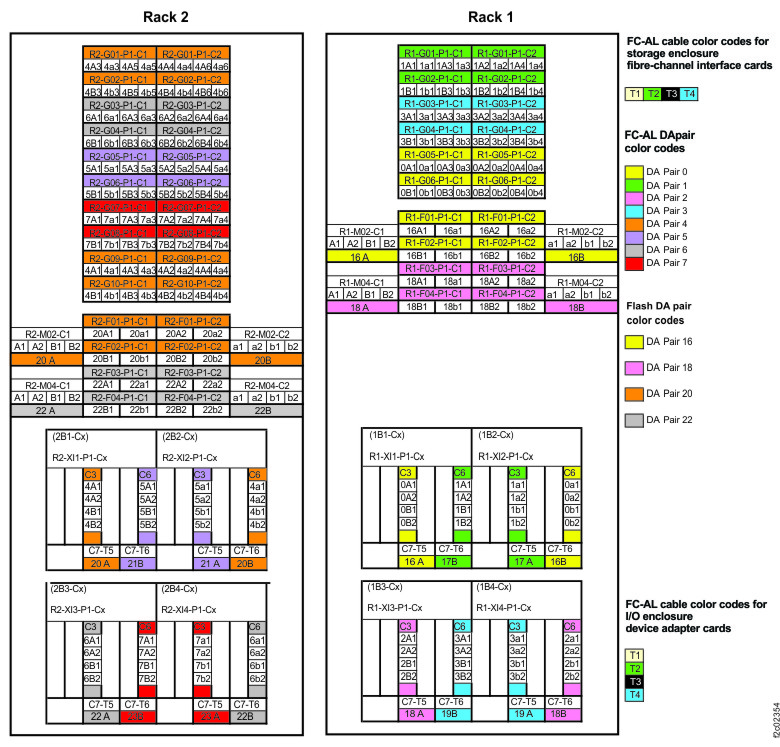
Figure 6. Point-to-point cabling diagram for storage enclosure FC-AL and Flash PCIe / SAS cables (Models 986, 86E, three-phase power, rear view, racks 1, 2) 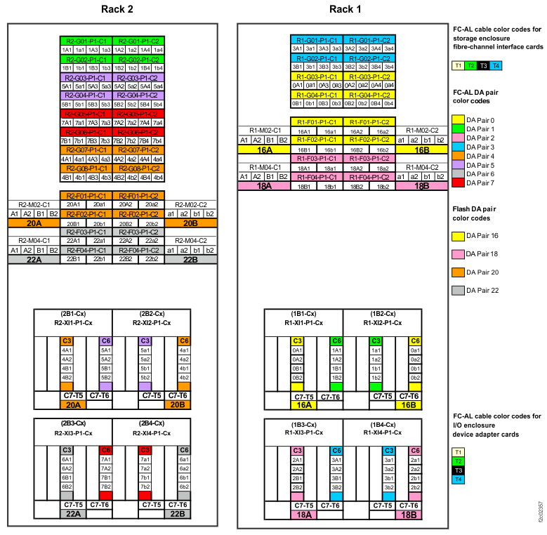
Figure 7. Point-to-point cabling diagram for storage enclosure Flash PCIe / SAS cables (Models 988, 88E, rear view, racks 1, 2) 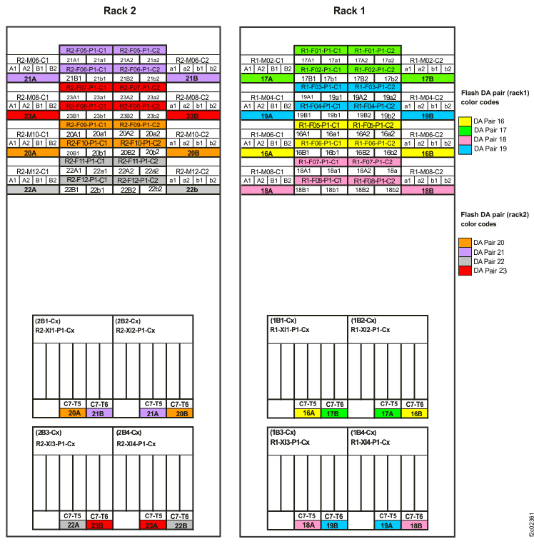
- To the question
MAP4963 Section-2, Error during flash enclosure installation
About this task
Procedure
Complete the following steps:
MAP4963 Section-3, Error isolation for power subsystem
You are here to diagnose if a fault in the power subsystem is a root cause of the reported serviceable event.
About this task
Procedure
| Step | Purpose | Decision | Next Step | Next Step Purpose | |
|---|---|---|---|---|---|
| A | Is there a PJA in the FRU List of the serviceable event? | Yes | B | Examine microbay power input LED | |
| No | Z | ||||
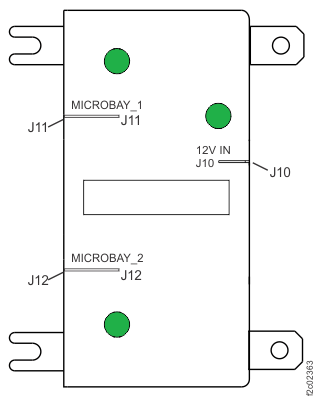
| B | Is the microbay power input LED lit? See Figure 9. If there is no microbay in the FRU list, then the decision for this step is "No." |
Yes | Z | ||
| No | C | Determine Microbay power input source. | |||
| C | Is this a Model 980, 981, or 982 ? | Yes | G | Check Microbay power input cable | |
| No | D | Examine PJA Output LED | |||
| D | Is the PJA power output LED (J11, J12) lit? See PJA locations within rack. | Yes | I1 | Isolated: power cable PJA-Microbay | |
| No | E | Check PJA power input LED | |||
| E | Is the PJA power input LED (J10) lit? See Figure 8. | Yes | I2 | Isolated: PJA | |
| No | F | Check PJA power input cable | |||
| F | Check the power cable from I/O enclosure to the PJA. Any cable that is disconnected or damaged? | Yes | I3 | Isolated: PJA power input cable | |
| No | I5 | Isolated: I/O enclosure PCIe Switch Card | |||
| G | Check the power cable from I/O enclosure to the Microbay. Any cable that is disconnected or damaged? | Yes | I4 | Isolated: Microbay power input cable | |
| No | I5 | Isolated: I/O enclosure PCIe switch card | |||
| I1 | Problem is isolated to the power cable between the PJA and microbay. The FRU to repair is
not listed in the FRU list of this serviceable event. Do the following steps:
|
End of procedure | |||
| I2 | Problem is isolated to the PJA.
|
End of procedure | |||
| I3 | Problem is isolated to the PJA power input cable. The FRU to repair is not listed in the
FRU list of this serviceable event. Do the following steps:
|
End of procedure | |||
| I4 | Problem is isolated to the Microbay power input cable. The FRU to repair is not listed in the FRU list of this serviceable event. Do the following steps:
|
End of procedure | |||
| I5 | Problem is isolated to the I/O enclosure PCIe Switch Card.
|
End of procedure | |||
| Z | Return to the step in MAP4963 where you branched to this section of the MAP. | There is no problem in the power subsystem. Pick up where you left off with existing flow of MAP4963 (examine PCIe Cable connectivity) |
|||
MAP4963 Section-4 Reference
About this task
Use the following references when you progress through the steps in MAP4963 Section-3, Error isolation for power subsystem.
Exchange the I/O enclosure to PJA power cable
Procedure
In Figure 8, J10 is an input and J11, J12 are outputs.
How to exit the MAP to proceed to the Exchange Parts menu
Procedure
- Return to the screen that sent you here.
- To the question, "What was the result of using the service procedure from Infocenter?" click Delay the repair and then click Next.
-
The current repair action ends, but the serviceable event is left open. Use the Exchange Parts
menu to exchange the targeted FRU (for example, PJA input cable, PJA output cable):
.
How to exit the MAP and proceed to repair a FRU in the FRU list
Procedure
Individual microbay LEDs
About this task
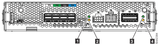
| Index | LED function | Location | Color | LED Off | LED On | LED Flash |
|---|---|---|---|---|---|---|
| 1 | Microbay power | P1-C7-Cx | Green | Power off | Power on | N/A |
| 2 | Microbay identify | P1-C7-Cx | Amber | Normal | N/A | Microbay identify |
| 3 | Microbay PCIe link status | P1-C7-Cx-T7 | Green | Link good | Link bad | N/A |
| 4 | Microbay PCIe port identify | P1-C7-Cx-T7 | Amber | Normal | N/A | PCIe port identify |
PJA locations within rack
About this task
Refer to Rack power and cooling location codes (Models 98x) (not 983).
Power distribution cables
Procedure
- Power distribution cables, Models 980, 98B
- Power distribution cables, Models 981, 98E (single-phase power)
- Power distribution cables, Models 981, 98E (three-phase power)
- Power distribution cables, Models 982, 98F
- Power distribution cables, Models 984, 84E
- Power distribution cables, Models 985, 85E (single-phase power)
- Power distribution cables, Models 986, 86E (three-phase power)
- Power distribution cables, Models 988, 88E all-flash
MAP2750 visual symptoms for power junction assembly (PJA) devices (Models 98x)
About this task
Refer to MAP2750 visual symptoms for power junction assembly (PJA) devices (Models 98x).